12
TROUBLESHOOTING
12.5 I/O Module Troubleshooting
12.5.2 Output Circuit Troubleshooting
12 - 261
9
EMC AND LOW
VOLTAGE
DIRECTIVES
10
LOADING AND
INSTALLATION
11
MAINTENANCE AND
INSPECTION
12
TROUBLESHOOTING APPENDICES INDEX
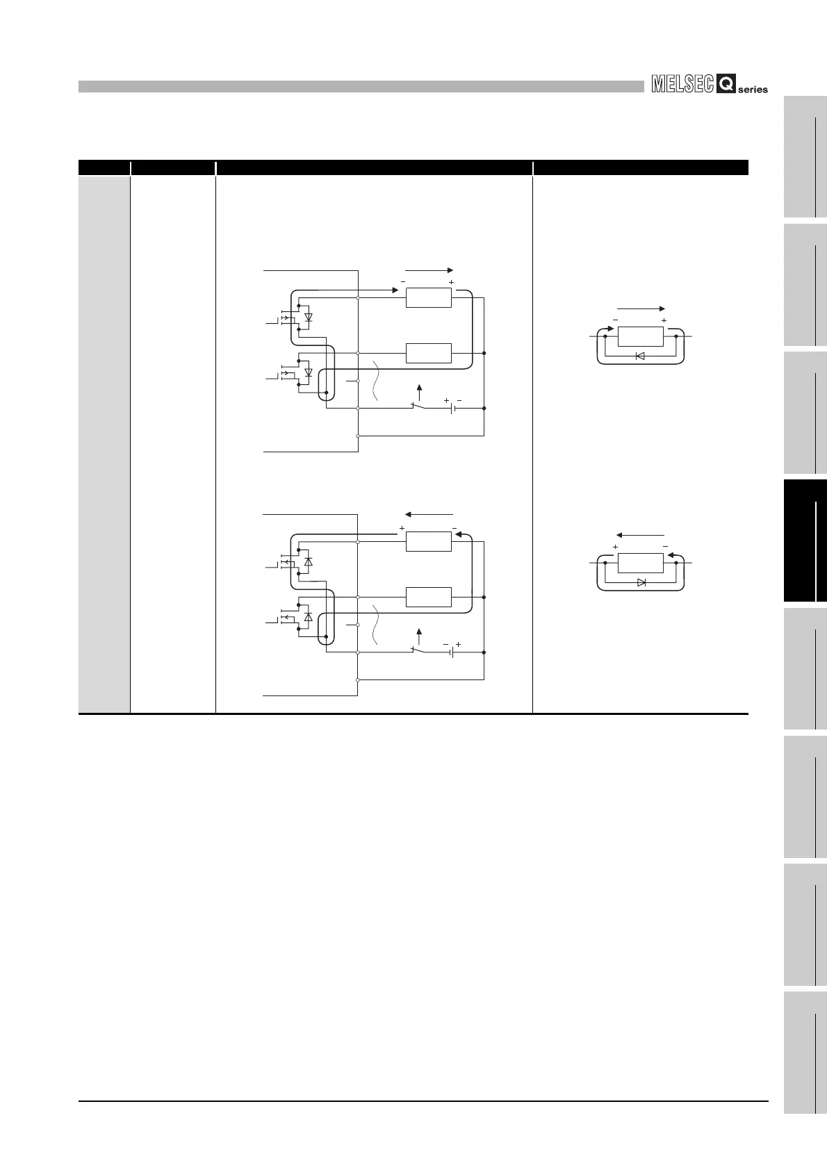
Table12.20 Output circuit troubleshooting (Continued)
Situation Cause Countermeasure
Example 5
The load which
was turned
OFF is turned
ON for a
moment at
power-off.
(Transistor
output)
The load [2] which was turned OFF may be turned ON due to
back electromotive force at the time of power-off [1] if an
inductive load is used.
To prevent the generation of the back
electromotive force, connect diode in
parallel with load where the back
electromotive force has been generated.
Source output
[3]
Sink output
[3]
[3]
[1]Shut off
TB1 ON
TB2 OFF
COM+
CTL-
ON
OFF
Output module,
combined module
Sink output
Back
electromotive
force
Load
Load
[2]
TB1 ON
Output module,
combined module
Sink output
Back
electromotive
force
Load
[1]Shut off
TB2 OFF
COM-
CTL+
ON
OFF
Load
[3]
[2]
Back
electromotive
force
Load
Load
Back
electromotive
force
 Loading...