12 - 356
12.8 Special Register List
12
TROUBLESHOOTING
(16) Process control instructions
(17) For redundant systems (Host system CPU information
*1
)
SD1510 to SD1599 are only valid for redundant systems.
They are all set to 0 for stand-alone systems.
*1: The information of the host CPU module is stored.
Table12.59 Special register
Number Name Meaning Explanation
Set by
(When Set)
Corres-
ponding
ACPU
D9
Corresponding
CPU
SD1500
SD1501
Basic period Basic period tome
• Set the basic period (1 second units) use for the process control
instruction using floating point data.
UNew
Q4AR
QnPH
SD1502
Process control
instruction detail
error code
Process control
instruction detail
error code
• Shows the detailed error contents for the error that occurred in the
process control instruction.
S (Error) New
SD1503
Process control
instruction
generated error
location
Process control
instruction
generated error
location
• Shows the error process block that occurred in the process control
instruction.
S (Error) New
SD1506
SD1507
Dummy device Dummy device • Used to specify dummy devices by a process control instruction. U New
QnPH
QnPRH
SD1508
Function
availability
selection for
process control
instruction
b0
Bumpless function
availability setting
for the S.PIDP
instruction
0: Enabled
1: Disabled
(Default: 0)
• Selects the availability (enabled/disabled) of the function for process
control instructions.
UNew
QnPH
QnPRH
Table12.60 Special register
Number Name Meaning Explanation
Set by
(When Set)
Corres-
ponding
ACPU
D9
Corresponding
CPU
SD1512
Operation mode
during CPU
module start up
Hot start switch
power out time
• Shows the power out time (S) during the automatic switch from hot start
to initial start in the operation mode when the CPU module is started up.
S (Initial) New Q4AR
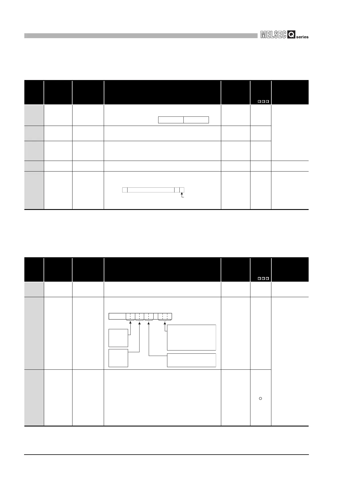
SD1585
Redundant
system LED
status
4 LED states
• BACKUP
• CONTROL
• SYSTEM A
• SYSTEM B
The LED status for BACKUP, CONTROL, SYSTEM A, SYSTEM B is
stored in the following format:
S (status
change)
New
QnPRH
SD1588
Reason(s) for
system
switching
Reason(s) for
system switching
that occurred in
host station
Stores the reason(s) for system switching on the host system.
The following values are stored corresponding to the methods for system
switching:
Initialized to 0 when the power supply is switched off and then on or the
RESET switch is set to the RESET position and then to the neutral
position.
0: Initial value (control system has not been switched)
1: Power off, Reset, H/W failure, WDT error,
2: CPU stop error (except WDT)
3: System switching request from network module
16: System switching dedicated instruction
17: System switching request from GX Developer
S (when
condition occurs)
SD1501 SD1500Floating point data =
b0b1b2b15 to
0
SD1508
00I/O
b14
Bumpless function
availability for the
S.PIDP instruction
b0tob2b3b4b5b6b7b8b10 b9b15
00
to
SYSTEM B
0: Off
1: On
2: Flicker
SYSTEM A
0: Off
1: On
2: Flicker
CONTROL
0: Off
1: On
BACKUP
0: Off
1: On (red)
2:
3: On(green)
4: Flicker(green)
Flicker(red)
5: On (orange-yellow)
6: Flicker
(orange-yellow)
 Loading...