2 - 17
2.1 System Configuration
2.1.1 System Configuration for Single CPU System
2
SYSTEM CONFIGURATION
(5) Outline of system configuration
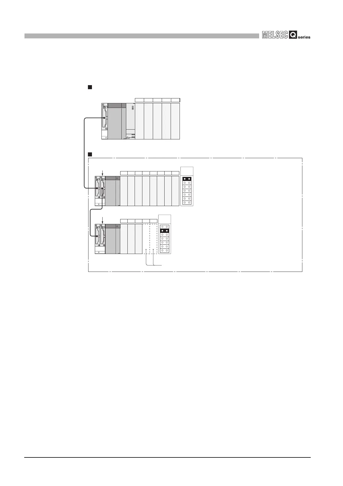
(a) When Q00JCPU is used
Diagram 2.16 System configuration when Q00JCPU is used
When module is mounted an error occurs.
Prohibited
Prohibited
....
I/O number
....
Slot number
1st
extension
base
2nd
extension
base
Q68B (8 slots occupied)
Q65B (5 slots occupied)
00 to 0F
10 to 1F
20 to 2F
30 to 3F
40 to 4F
50 to 5F
60 to 6F
70 to 7F
80 to 8F
90 to 9F
A0 to AF
B0 to BF
C0 to CF
D0 to DF
E0 to EF
F0 to FF
01234
5 6 7 8 9 101112
13 14 15 16 17
Q00JCPU The figure shows the configuration when 16-point modules are loaded to each slot.
...
Extension base unit The figure shows the configuration when 16-point modules are loaded to each slot.
...
 Loading...