App - 50 App - 50
MELSEC-Q
APPENDICES
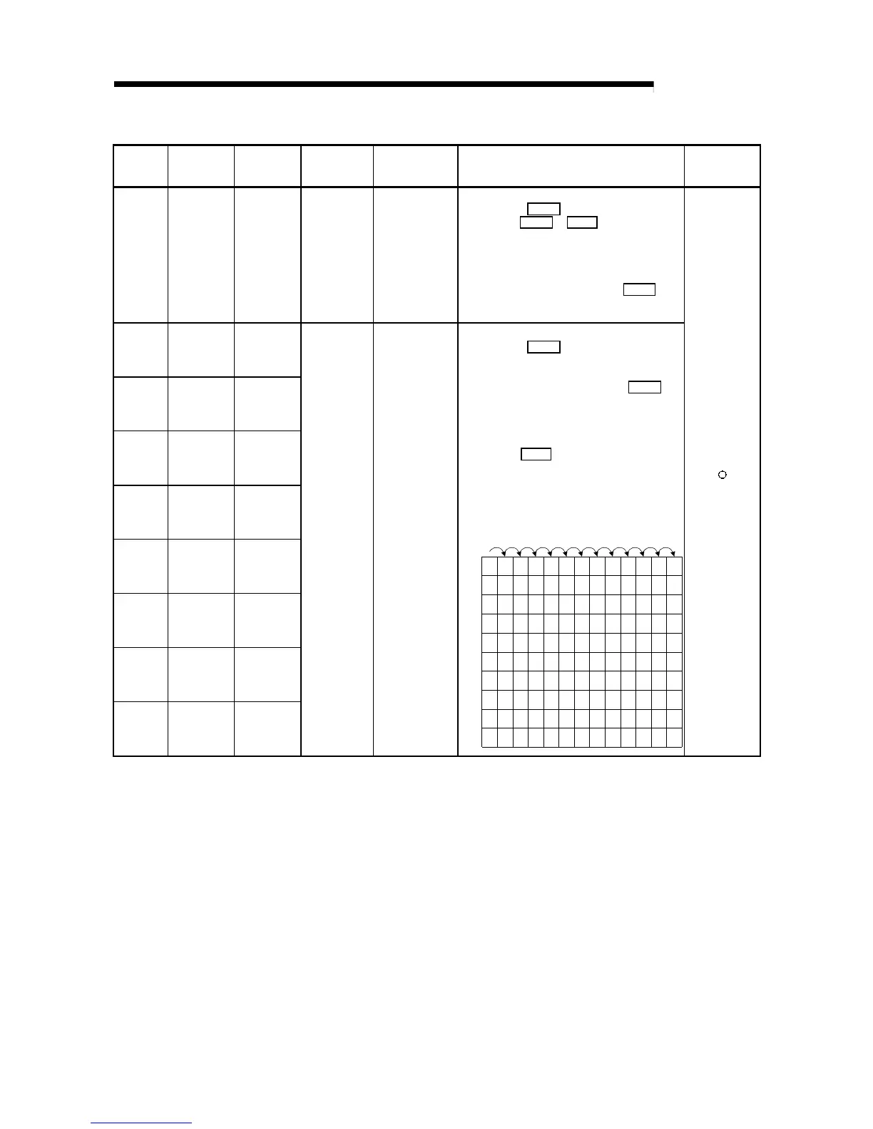
Special Register List (Continued)
ACPU
Special
Conversion
Special
Register after
Conversion
Special
Register for
Modification
Name Meaning Details
Corresponding
CPU
D9124 SD1124 SD63
Annunciator
detection
quantity
Annunciator
detection quantity
• When one of F0 to 255 (F0 to 2047 for AuA and AnU)
is turned on by SET F
1 is added to the contents of
SD63. When RST F
or LEDR instruction is
executed, 1 is subtracted from the contents of SD63.
(If the INDICATOR RESET switch is provided to the
CPU, pressing the switch can execute the same
processing.)
• Quantity, which has been turned on by SET F
is
stored into SD63 in BIN code. The value of SD63 is
maximum 8.
D9125 SD1125 SD64
D9126 SD1126 SD65
D9127 SD1127 SD66
D9128 SD1128 SD67
D9129 SD1129 SD68
D9130 SD1130 SD69
D9131 SD1131 SD70
D9132 SD1132 SD71
Annunciator
detection
number
Annunciator
detection number
• When one of F0 to 255 (F0 to 2047 for AuA and AnU)
is turned on by SET F
, F number, which has turned
on, is entered into SD64 to SD71 in due order in BIN
code.
• F number, which has been turned off by RST F
, is
erased from SD64 to SD71, and the contents of data
registers succeeding the data register, where the
erased F number was stored, are shifted to the
preceding data registers.
• By executing LEDR
instruction, the contents of
SD64 to SD71 are shifted upward by one. (For A3N,
A3HCPU, it can be performed by use of INDICATOR
RESET switch on front of CPU module.)
• When there are 8 annunciator detections, the 9th one
is not stored into SD64 to SD71 even if detected.
0 505050505050505050505099
0
0 5050505050505050505099
0 2525999999999999999915
123234567888
50
0
0 99 1515151515151570
00 0
0 70707070707065
00 000
0 65656565653800 0000
0 38383838
110
00 0000
0
0 110 110 110
151
00 0000
0
0 151 151 210
00 0000
0
0
00
 Loading...


