2 Robot arm
Outside dimensions ・ Operating range diagram
2-16
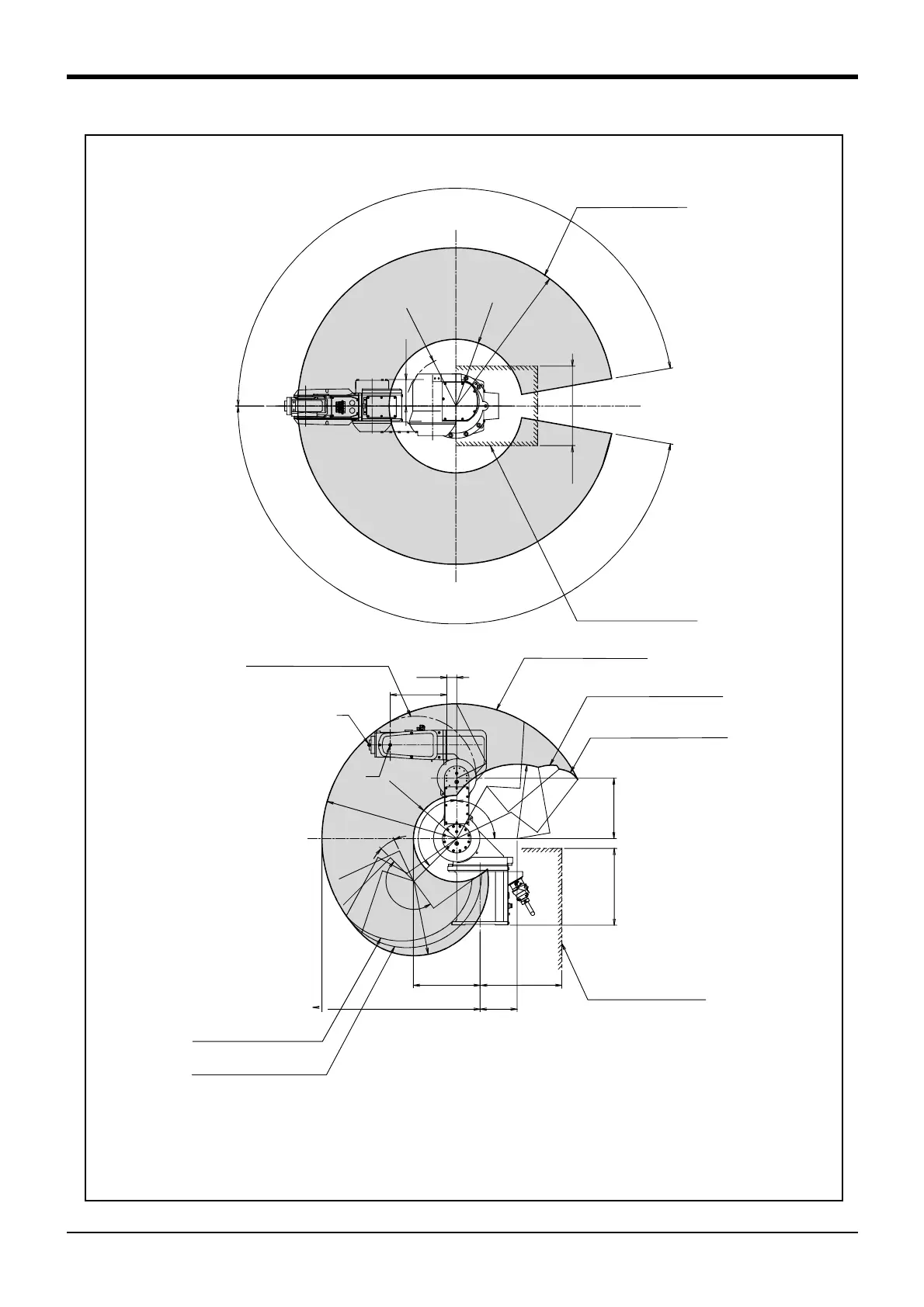
Fig.2-4 : Operating range diagram: RV-3S/3SC
150
642
271
R
R
54
7
R17
6
R
3
0
2
R
3
0
2
245
90°
1
3
5
°
1
71
°
40
230
R
64
2
1
7
0
°
1
7
0
°
R
27
1
R
2
0
3
322
109
P-point path (solid line)
The range which
P-point cannot enter
2
0
°
312
330
Flange downward limit line
(dotted line)
P-point path (solid line)
Restriction on wide angle
in the rear section
Note4)
Restriction on wide angle
in the rear section
Note3)
P
Restriction on wide angle
in the front section
Note1)
Restriction on wide angle
in the front section
Note2)
The range which
P-point cannot enter
<Restriction on wide angle in the front section>
Note1) If the angle of axis J1 is 170 degree > J1 > 125 degree,
the operating range of axis J2 is limited to 125 degree > J2> -90 degree.
Note2) If the angle of axis J1 is -125 degree > J1 > -170 degree,
the operating range of axis J2 is limited to 130 degree > J2 > -90 degree.
<Restriction on wide angle in the rear section>
Note3) If the angle of axis J2 is -30 degree > J2 ≧ -60 degree,
the operating range of axis J3 is limited to a range
that satisfies both 4 x J2 + 3 x J3 > -180 and 171 degree > J3 > -20 degree.
Note4) If the angle of axis J2 is -60 degree > J2 ≧ -90 degree,
the operating range of axis J3 is limited to a range
that satisfies both 2.7 x J2 + 3 x J3 > -142 and 171 de
ree > J3 > -20 de
ree.
 Loading...


