3-47
Parallel input/output unit
3 Controller
3.7 Parallel input/output unit
・ A parallel input/output card is mounted as a standard in the controller's control unit.
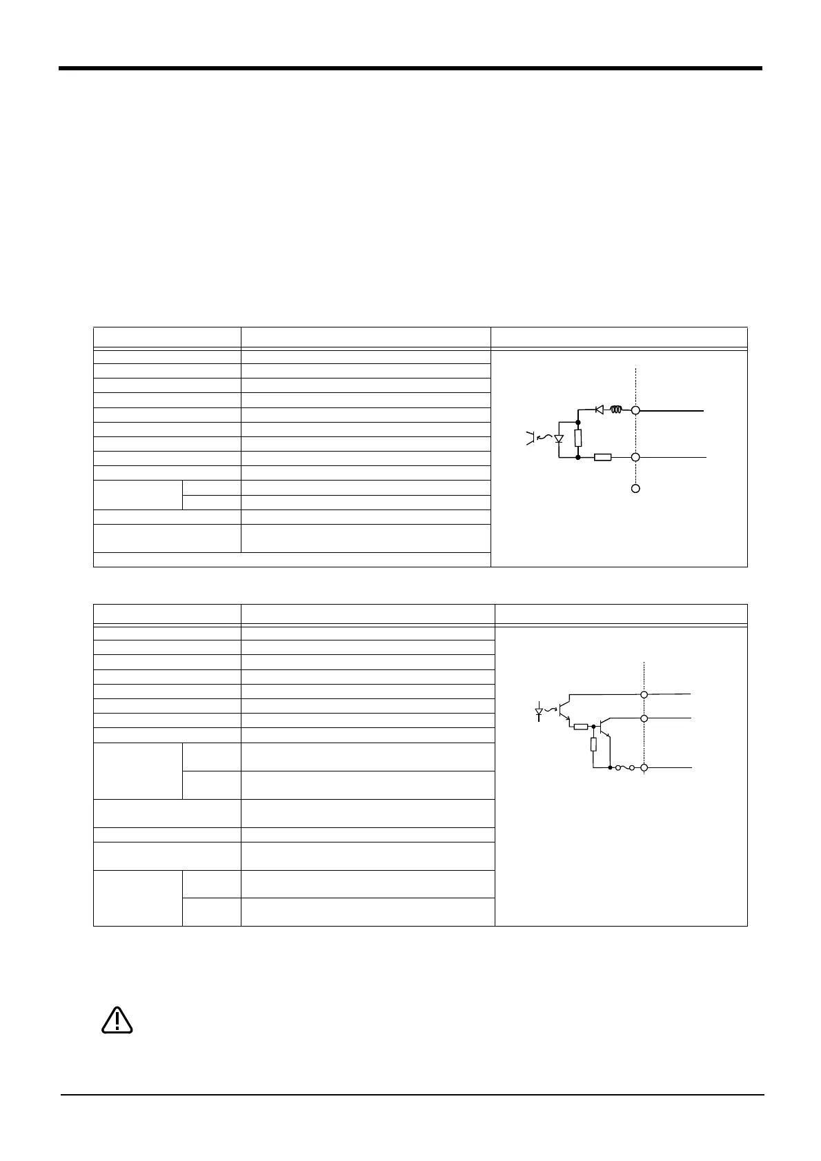
・ The external input/output circuit specifications are shown in Table 3-4 and Table 3-5.
・ The correspondence of the external input/output connector pin No. and the colors of the connected "external
input/output cable" wires (separate option) is as shown in
Page 48, "Table 3-6". Refer to Page 70, "(6) External
I/O cable" for details of external I/O cable.
・ Pin Nos. described as both general-purpose signal and dedicated signal can be shared.
・ The other dedicated input/output signals that are not assigned can be assigned to required general-purpose
input/output pins when creating the program.
・If the standard inputs and outputs are insufficient, install the parallel input/output unit connection option outside
the controller.
Table 3-4 : Electrical specifications of input circuit
Table 3-5 : Electrical specifications of output circuit
[Caution] When connecting the phototransistor output to the input circuit, be sure to allocate an input current of
approximately 7 mA at 24 VDC. Especially when using a photo diode and a phototransistor (sensor)
away from each other, it is recommended to verify the current that can be carried in the design stage.
The output circuit protective fuses prevent failure in case of load short-circuit and
improper connections.
Please do not connect loads that cause the current to exceed
the maximum rated current. If the maximum
rated current is exceeded, the internal
transistors may be damaged.
Item Specifications Internal circuit
Type DC input
No. of input points 16
Insulation method Photo-coupler insulation
Rated input voltage 12VDC/24VDC
Rated input current Approx. 3mA/approx. 7mA
Working voltage range 10.2VDC to 26.4VDC(ripple rate within 5%)
ON voltage/ON current 8VDC or more/2mA or more
OFF voltage/OFF current 4VDC or less/1mA or less
Input resistance Approx. 3.3kΩ
Response time
OFF-ON 10ms or less(DC24V)
ON-OFF 10ms or less(DC24V)
Common method 8 points per common
External wire connection
method
Connector
Item Specifications Internal circuit
Type Transistor output
No. of output points 16
Insulation method Photo-coupler insulation
Rated load voltage DC12V/DC24V
Rated load voltage range DC10.2 ~ 30V(peak voltage 30VDC)
Max. load current 0.1A/point (100%)
Leakage current at OFF 0.1mA or less
Max. voltage drop at ON DC0.9V(TYP.)
Response time
OFF-ON
2ms or less
(hardware response time)
ON-OFF
2ms or less
(Resistance load) (hardware response time)
Fuse rating Fuse 3.2A (one per common) Replacement not pos
-
sible
Common method 8 points per common (common terminal: 8 points)
External wire connection
method
Connector
External power
supply
Voltage DC12/24V(DC10.2 ~ 30V)
Current
60mA (TYP. 24VDC per common)
(base drive current)
3.3K
Input
820
24V/12V
(COM)
(24/12V)
Outline
(0V)
Fuse
CAUTION
 Loading...


