3 Controller
Parallel input/output unit
3-48
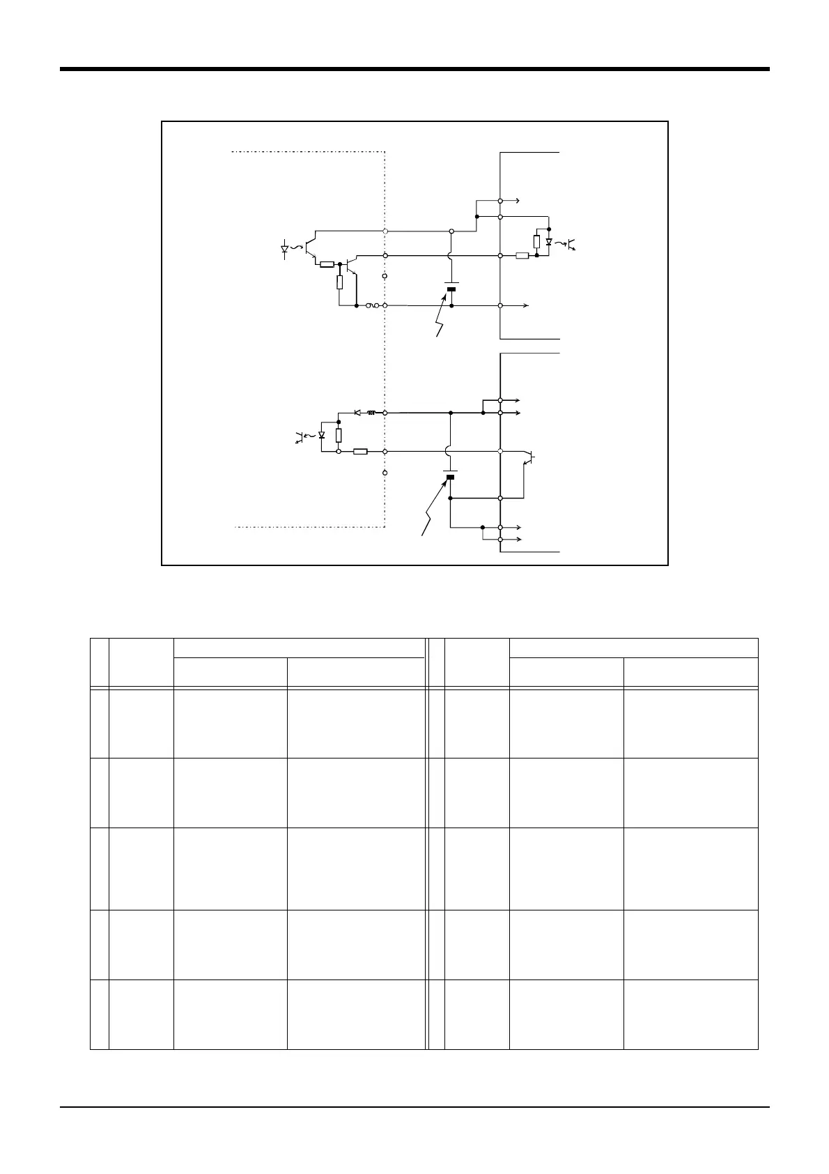
Fig.3-7 : Connection with a Mitsubishi PLC (Example of sink type)
*The input/output circuit external power supply (24 VDC) must be prepared by the customer.
Table 3-6 : Standard parallel I/O interface CN100pin No. and signal assignment list (2A-CBL □□ )
Pin
No.
Line color
Function name
Pin
No.
Line color
Function name
General-purpose Dedicated/power supply, common General-purpose
Dedicated/power supply,
common
1 Orange/Red A FG 26 Orange/Blue A FG
2 Gray/Red A 0V:For pins 4-7, 10-13 27 Gray/Blue A 0V:For pins 29-32, 35-38
3 White/Red A 12V/24V:For pins 4-7 28 White/Blue A 12V/24V:For pins 29-32
4 Yellow/Red A General-purpose output 0 Running 29 Yellow/Blue A General-purpose output 4
5 Pink/Red A General-purpose output 1 Servo on 30 Pink/Blue A General-purpose output 5
6 Orange/Red B General-purpose output 2 Error 31 Orange/Blue B General-purpose output 6
7 Gray/Red B General-purpose output 3 Operation rights 32 Gray/Blue B General-purpose output 7
8 White/Red B 0V:For pins 4-7, 10-13 33 White/Blue B 0V:For pins 29-32, 35-38
9 Yellow/Red B 12V/24V:For pins 10-13 34 Yellow/Blue B 12V/24V:For pins 35-38
10 Pink/Red B General-purpose output 8 35 Pink/Blue B General-purpose output 12
11 Orange/Red C General-purpose output 9 36 Orange/Blue C General-purpose output 13
12 Gray/Red C General-purpose output 10 37 Gray/Blue C General-purpose output 14
13 White/Red C General-purpose output 11 38 White/Blue C General-purpose output 15
14 Yellow/Red C COM0:(12V/24V(COM))For pins
15-22
39 Yellow/Blue C COM1:(12V/24V(COM))For pins
40-47
15 Pink/Red C General-purpose input 0
Stop(All slot)
Note1)
Note1)The assignment of the dedicated input signal "STOP" is fixed.
40 Pink/Blue C General-purpose input 8
16 Orange/Red D General-purpose input 1 Servo off 41 Orange/Blue D General-purpose input 9
17 Gray/Red D General-purpose input 2 Error reset 42 Gray/Blue D General-purpose input 10
18 White/Red D General-purpose input 3 Start 43 White/Blue D General-purpose input 11
19 Yellow/Red D General-purpose input 4 Servo on 44 Yellow/Blue D General-purpose input 12
20 Pink/Red D General-purpose input 5 Operation rights 45 Pink/Blue D General-purpose input 13
21 Orange/Red E General-purpose input 6 46 Orange/Blue E General-purpose input 14
22 Gray/Red E General-purpose input 7 47 Gray/Blue E General-purpose input 15
23 White/Red E Reserved 48 White/Blue E Reserved
24 Yellow/Red E Reserved 49 Yellow/Blue E Reserved
25 Pink/Red E Reserved 50 Pink/Blue E Reserved
60mA
(24/12V)
Output
Fuse
(0V)
(COM)
AX41C
(Mitsubishi programmable
controller)
AY51C
(Mitsubishi programmable
controller)
+24V
24V
COM
X
Y
24V
…
…
Input
Parallel I/O interface
(Output)
(Input)
3.3K
CTL+
Output
Input
External
power supply
CTLG
24G
COM
External
power supply
24G
24V
…
…
 Loading...


