3 Controller
Expansion option box
3-60
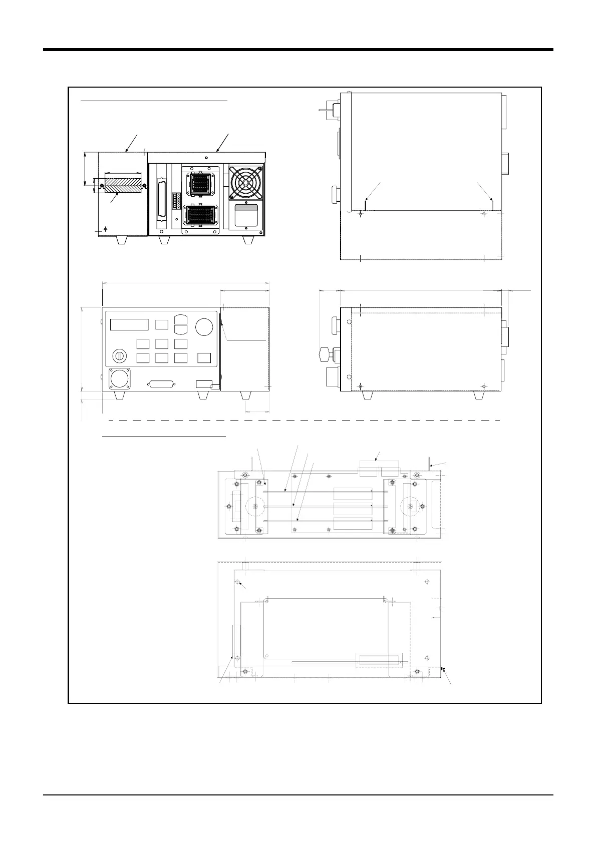
Fig.3-16 : Outside dimensions and layout
■ Installation method
Remove the side plate of the controller, connect the connectors, and fix to the controller with the four fixing
screws in the expansion option box.
The option cards mounted in the slot are fixed with the plates with rails.
The cables required for the option card are lead out from the cable outlet on the rear side.
(38)
290
(13)
299.7
87.5
151
(15)
42
Installation of expansion option box
Positioning latch Positioning latch
Installation
screw
Four
positions
Expansion option box
Controller
60
65
24
Rear side
cable outlet
Slot1
Slot2
Slot3
Controller connection connector
Fan
Installation screw(Four positions)
Grounding terminal(M4)
Plates with rails
(Two positions)
Layout of expansion option box
Positioning latch
The example which an option
card was mounted to.
 Loading...


