MAINTENAN
CE
AND ADJUSTMENT
.l
•...
~ ~
....
~
.....
-
~
.....
...
"
....
l
..
ujScSluic::
I.;au~>
iJ.su
::
J
in
lOJSi
Io!Ul"':
.
','vhal?e regulator is set
[0
m:
untain lOa hi¢1 a
vo
j
ta/lC:
.1
; ..-
_""':"
.....
:.
':'"
- '
......
.
....
,.
;:.med.
The
batterv i
'S
iflternallv
:non·circuireci.
~
~~r:,;
!:';:'j~ly
.
J
He
diL'CiLlLiu,)l
J:!<.
rHltUlti..:ln2
I
n
....
t
~..,"'
., f".,
........
''''''~
hU~
";
;
CUIU
H~
tllOUe
n~Clliler
mllP
nf!
T
P~
i'
....
ltI.:t"t
L<LHl
wmll
IS
nrevenTln~
1nl'
:<!IU'l'nalhr
:
--
j
_:;
~~
;
....
i.w.
.....
.:.
.
Ui
...
i"':'
..
;:
; 1
'"
i.':'.,ji v ...........
aJlU
~;;..:
't1lt:m';U
l
!T
~naJ
I
to
lIle
vanao~e·sp~
:
:
!.::.::~~
lt110lOt
1
Ul
ttU:
oencn.
roMe:
elecu
I· .
H)m
l
a.
ItS
\"
CirCUit arrang.e!!
as
shown
:
.!...-.
)
SlOtl
teh
J(.
~
.
~
SWJt!:~
' .
•
- I
a
'
~r---f
.
~
-i
S::me-rv
I
'1
,
.li
~
82
"
•
0
....
r
..
~_~
_ .
..
. _
\VJth
S\':
~
~;;
t
; .
.....
.
~~_
1,.
.....
""""I~'"
.u
...
~",
...
'
"ator
field from the battery), drive the alter·
nalor by
tUTning
on
th
e drive motor, increasing
the speed
of
drive graduaUy, and observe
the
indications
of
the voltmeter and ammelfr.
Stop
increasing the speed when the ammeter indica·
tlon
reaches Its zero
mark,
and open switch
Kl
:
~
!:e
:.r
.....
rJl.:~niJl
i.:;:rmmm
or
11:;;
rcC::1il;:>
';
......
_ ..... _ ..
_--
..• _ .
..
- .
•
,,'
,. 'v . •.
....
.."
r.
" .
..
-
~.
---
_
..
_---
-
..
-- --: -
,,
-
-:.
-'
unit develoos
the
rale
c
vo
ltage.
~~~
~r:.:""
.:;:
11
l~p
dOOUI
1
iO
O
rom
.
Next. close
SWltcn
1\.1 • ..
It!!
~1i.~
':"~!1
:
!~!e
~:
:~!1
...~
••
,.,
p.nlt~llv
(tr
.::
u111;1l
lv
~nn
r
p'!lrl
..
"',.
.................
' o r
'1!
r"'~
"':"'''''
l '
'''
.: .....
~
.~
- .
·o.jic!K:
lc:.c
..
iUI.:!I
IVU~UUl
~'I.IIIC;II~
.111l1
~
ll[
'~Ul
Willi
Ule:
oerrOrmance
Spe
CUlcatlO
nS
to
Uel.emUne-
wnetner or not t
he
alterna.tor
unit
is.
capable
of
me
soecitJeCl
OUluut Der
fm::m
ance.
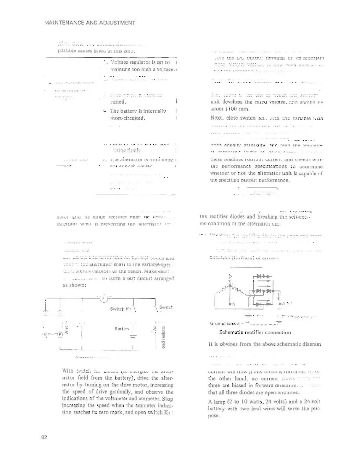
the rectifier diodes and bu:akine:
the
sei:;
·exc:·
tn2 conalUon
or
tne alternator un:
· 1.
......
1.:
__
.1..
-
...
..
~
i
r;
."
;.'_
' .
..:.
.;':'
•.
:~j'::'
.
"
i..
.....
nQ'UJ
Vl
G I
\Vh
.1~
.:,,,,r,,
I
i L r - '1'"
lire-uno
C.
!~
Cl!
.
~
.
...-;
_____
__
-::-
Schematic rectifier
connection
Il is obvious
from
the
abo.,.e
schematic d
i,Hmlln
It"..UlII[;JLl
ww
lIUW
II
dUY
UJUut:.
I::'
IUULUL~U.
::.
c.:.:
the
other
hand
.
no
current
:;=
..
-
:~
_.
---
Uuee
are biased in iorw3ra OJrecnon .
..
(hat all three diodes are opc::n-cncuneu.
A lamp (2
to
10
wallS,
24
volts)
and
a 24-vol.
battery
with two lead wiles w
ill
serve the pur·
pos • .
 Loading...


