Chapter Two: Installation Interface Connecto
17
Interface Connector
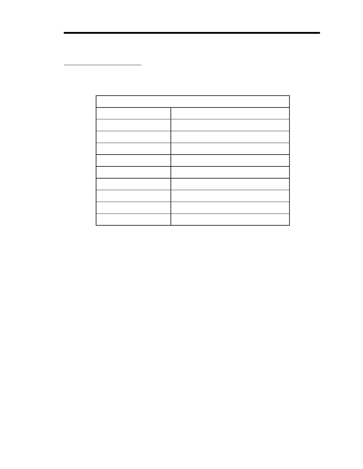
The pinout of the 9 -pin Type “D” Interface connector is shown in Table 8.
Interface Connector Pinout
Pin Number Signal
1 Motor Winding A
2 Motor Winding A'
3 Limit Switch Common
4 Open Limit Switch
5 Closed Limit Switch
6 Motor Winding B
7 Motor Winding B'
8 Limit Switch Current Source
9 No Connection
Table 8: Interface Connector Pinout
The limit switches require 25 mA current. For proper operation, use a +15 VDC power supply
run through a 470 ohm, 0.5 Watt resistor.
To set up the Type 651, 1651, or 652B pressure controller, refer to the corresponding instruction
manual.