Chapter Two: Installation Flan
e T
es
13
JIS Series Flanges
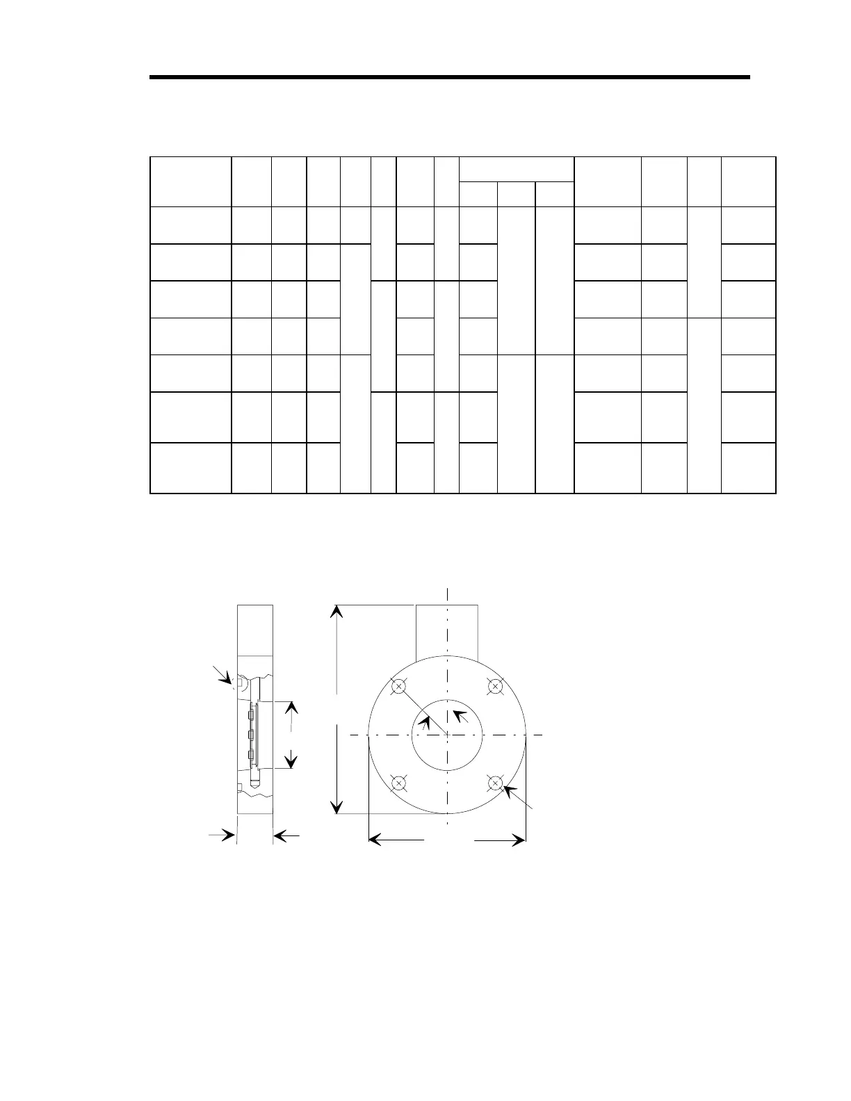
Model No. A B C E F G H J O-Ring Groove O-Ring K L Total
I.D. Width Depth Size Height
653 -2-50J-1
653 -2-50J-2
1.886
(48)
4.47
(114)
5.906
(150)
0.39
(10)
4 3.937
(100)
45º 2.766
(70)
0.197
(5)
0.118
(3)
2.756 x 0.157
(70 x 4)
JIS
50MM
1.00
(25)
11.97
(30.4)
653 -3-80J-1
653 -3-80J-2
2.886
(73)
6.299
(160)
6.524
(166)
.472
(12)
5.315
(135)
3.937
(100)
3.937 x .157
(100 x 4)
JIS
80MM
12.58
(320)
653 -4-100J-1
653 -4-100J-2
3.885
(99)
7.28
(185)
7.53
(191)
8 6.299
(160)
22.5º 4.724
(120)
4.724 x .157
(120 x 4)
JIS
100MM
13.59
(345)
653 -6-150J-2 5.709
(145)
9.25
(235)
10.14
(258)
8.268
(210)
6.890
(175)
.157 x 6.811
(4 x 173)
JIS
150MM
1.62
(41)
16.20
(411)
653 -8-200J-2 7.677
(195)
11.81
(300)
12.72
(323)
0.590
(15)
10.630
(270)
8.858
(225)
0.315
(8)
0.177
(4.5)
0.236 x 8.760
(6 x 222.5)
JIS
200MM
18.78
(477)
653 -10-250J-2 9.645
(244.9)
13.78
(350)
14.71
(374)
12 12.598
(320)
15º 10.827
(275)
0.236 x
10.709
(6 x 272)
JIS
250MM
20.77
(528)
653 -12-300J-2 11.597
(294.5)
15.75
(400)
16.68
(424)
14.566
(370)
12.795
(325)
0.236 x
12.658
(6 x 321.5)
JIS
300MM
22.74
(578)
Table 5: Size Options for JIS Series Flanges
H
L
C
Groove J
O-Rin
Supplied by
Customer
A Dia.
B Dia.
Mates with K JIS Flan
e
E = Dia. of the Hole
F = Number of Holes, Equally Spaced
G = Dia. from Hole to Hole
Figure 5: Outline Dimensions of a JIS Series Flange