31
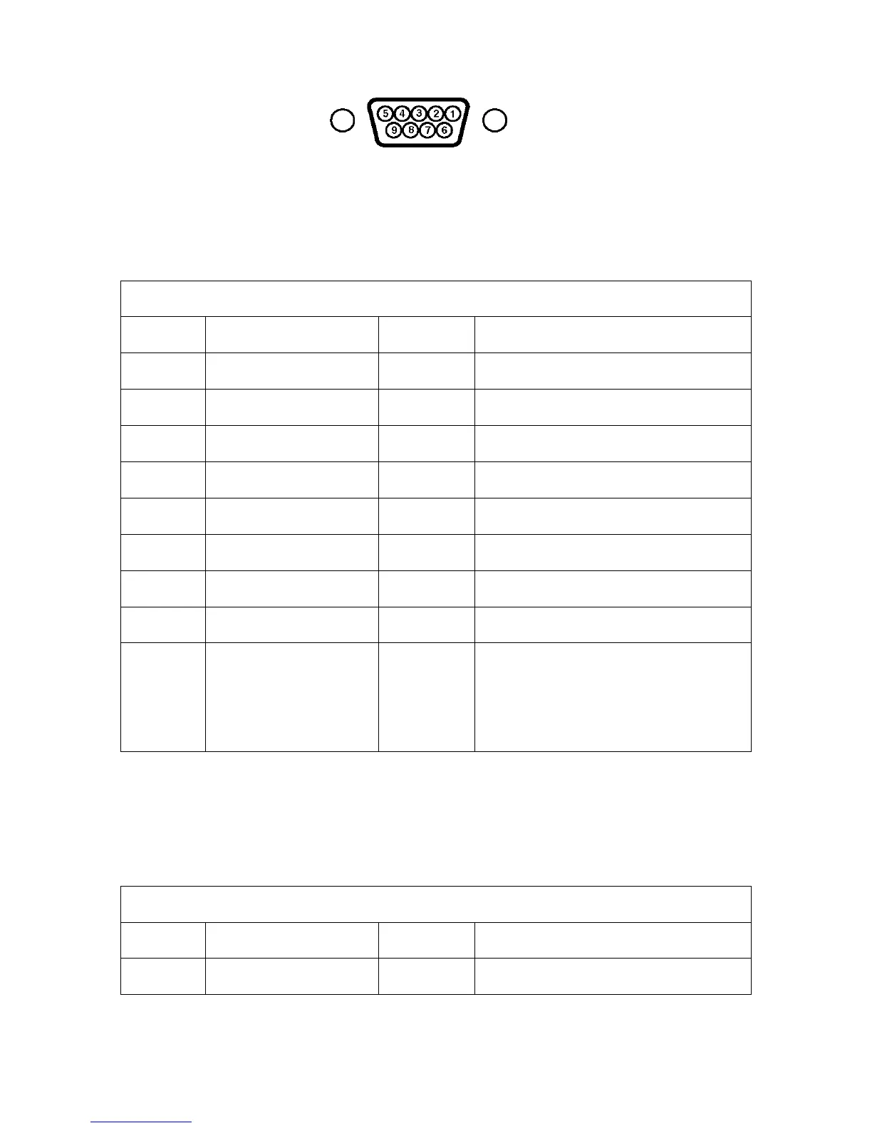
Figure 4: Model PDR 2000 Sensor Connector – 9 Pin Female D-Sub Connector
The following information allows you to make modifications to the cable as needed to interface with
your CDG. Refer to the above figure. This shows the 9-pin connector, which is on the rear panel of the
PDR 2000. This connector has female sockets; the mating connector on the CDG cable must have male
pins.
PDR 2000 9-Pin ‘D’ – MKS Baratron 15-Pin ‘D’ Connections
PDR Pin MKS Name Color Tube Pin/Connection Name
1 Tube #1 Signal White Tube#1, Pin 2/Signal Output
2 Tube #2 Signal White Tube#2, Pin 2/Signal Output
3 Tube #2 Signal Return Brown Tube#2, Pin 12/Signal Common
4 +15 volts Red Tube#1, Pin 7/+15 VDC
5 +15 volts Red Tube#2,Pin 7/+15 VDC
6 -15 volts Green Tube#1, Pin 6/-15 VDC
7 -15 volts Green Tube#2, Pin 6/-15 VDC
8 Tube #1 Signal Return Brown Tube#1, Pin 12/Signal Common
9 Electronics Common
Black/shield
.
Black/shield
Tube#1, Pins 5/Pwr.Comm & 15/&
Chassis Gnd
Tube#2,Pins 5/Pwr.Comm &
15/&Chassis Gnd
Table 2: PDR 2000 9-Pin ‘D’ - MKS Baratron 15-Pin ‘D’ Connections
PDR 2000 9-Pin ‘D’ - MKS Baratron 5-Pin Phoenix Connections
PDR Pin MKS Name Color Tube Pin/Connection Name
1 Tube #1 Signal White Tube#1, Pin 3/Signal Output