33
Making Accessory Connections
The 15-pin D-sub Accessory Connector is on the rear panel of the PDR 2000. The connector has female
pins. The mating connector must have male pins. Mating D-sub 15 connectors are available from many
of the normal electronic sources. If you need help identifying a source, please contact us.
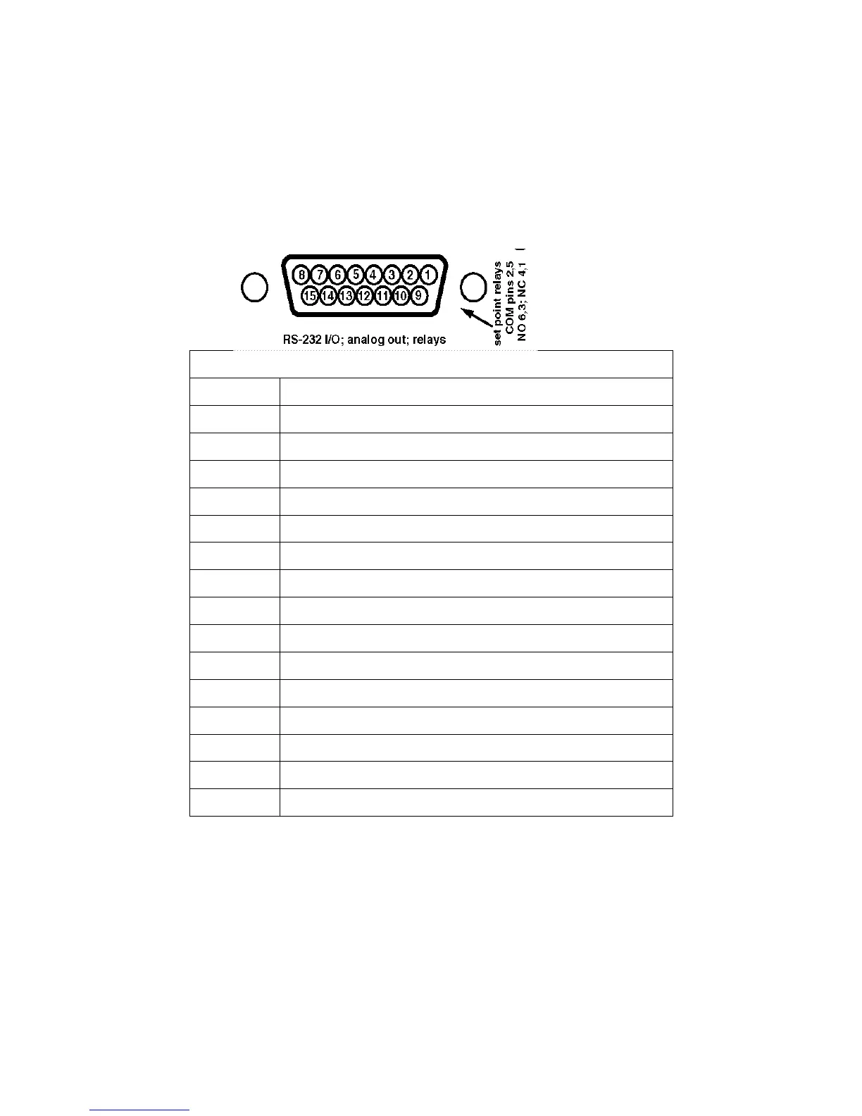
Figure 5: RS-232 I/O; Analog Out; Relays
The following are pin assignments for the Accessory Connector.
PDR 2000 15 Pin - Accessory Connector Signals and Pins
15-pin Accessory Connector
Pin 1 Set point #1 relay, normally closed
Pin 2 Set point #1 relay, common
Pin 3 Set point #1 relay, normally open
Pin 4 Set point #2 relay, normally closed
Pin 5 Set point #2 relay, common
Pin 6 Set point #2 relay, normally open
Pin 7 Tx, RS-232 signal out of the PDR 2000; 9600-N-8-1
Pin 8 Rx, RS-232 signal into the PDR 2000
Pin 9 Ground, RS-232 and analog common
Pin 10 No function
Pin 11 CDG#2 buffered analog signal; 1K output
Pin 12 No function
Pin 13 Analog output, 1K output, 0.5 volts/decade
Pin 14 No function
Pin 15 CDG# 1 buffered analog signal; 1K output
Table 4: PDR 2000 15 Pin - Accessory Connector Signals and Pins