Instructions for use
30 CLIMACELL EVO_np_en_1401_mmm_V1.01
- Exposition – the segment is terminated in case
that there was reached the required exposition of
visible light (klx.h) or UV radiation (mW.h/cm
2
).
The exposition selection is possible only at
devices with exposition lighting and sensors for
measuring the light intensity (see 6.10 and 6.11).
For setting of programs with light exposition see
8.4.4.1.
(7) Number of cycles.
- May be set within the range 1 to 9999.
(8) Infi nite last segment.
(9) Selection of programs chaining.
- Another program may follow after the program
termination.
(10) The following program selection.
8.4.2.1 SAFETY THERMOSTAT
The safety thermostat is used to protect the exposed
material, the incubator itself and its surroundings if the
temperature in the chamber of the device exceeds (falls
below) the maximum (minimum) limit or in the case of
regulation complications. Depending on setting of the option
(3) and (4), Fig. 53 during activation of protective thermostat
there is announced warning (
) or fault ( ).
For more details, see 8.3.3.
● If, during regulation, the temperature moves beyond the
monitored zone, the heating (cooling) is disconnected.
If the temperature spontaneously moves back within the
permissible zone, regulation recommences. The device
acts as if a warning has occurred.
● If, during regulation, the temperature moves beyond the
monitored zone, the heating (cooling) is permanently
disconnected. Regulation cannot continue without the
operator’s intervention. The device acts as if an error
has occurred.
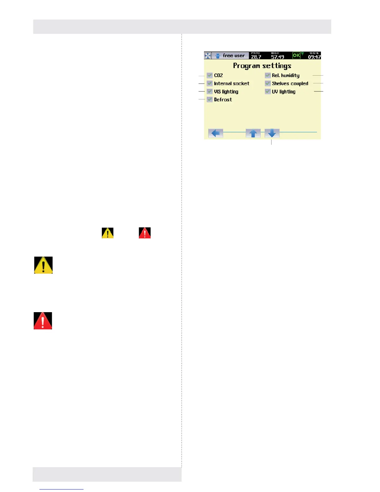
8.4.3 PROGRAM CONFIGURATION
This menu is used to select variables and accessories that
are to be active in the program in question.
Notes:
- The variables that can be selected in this menu depend
on the specifi c confi guration of the device
- The options CO
2
, Internal socket, UV lighting, VIS
lighting, Defrosting are only available on devices with the
appropriate optional equipment,see 6.9, 6.10, 6.14.
Fig. 54
(1) CO
2
- Optional device accessories.
- For devices with CO
2
regulation.
(2) Internal socket.
- Optional device accessories, see 6.9.
- In the course of the program, this socket may be
switched on (switched off), see 8.4.4.
(3) Light exposition – visible light
- Optional device accessories, see 6.10.
- For devices with lighting on light racks (visible
light).
(4) Automatic defrosting of cooling system
- Optional device accessories.
- This option should be used particularly for
programs with long-term and intense cooling,
when the condensate on the cooling unit gradually
freezes, thus reducing effi ciency. If this option is
activated, the heating medium will be injected into
the cooling system at regular intervals (depending
on the program settings and the specifi c type of
device), which will remove any ice. This is done to
minimise the impact on temperature and humidity
regulation in the working part of the incubator;
for the duration of this operation the fan speed is
reduced to 10 %.
- We recommend using this within the temperature
range from 0 °C to the ambient temperature.
(5) Transfer to segments editing.
(6) Relative humidity.
(7) Coupled racks.
- Option only for devices with UV or VIS racks
(6.10.2).
- In case of active selection, all the UV racks
(respectively all the VIS racks) are controlled
simultaneously.
If the option is not ticked, every rack is controlled
independently.
(8) UV exposition.
- Optional equipment of the device, see 6.10.2.
(5)
(1)
(2)
(3)
(4)
(6)
(7)
(8)