6 CLIMACELL EVO_np_en_1401_mmm_V1.01
Instructions for use
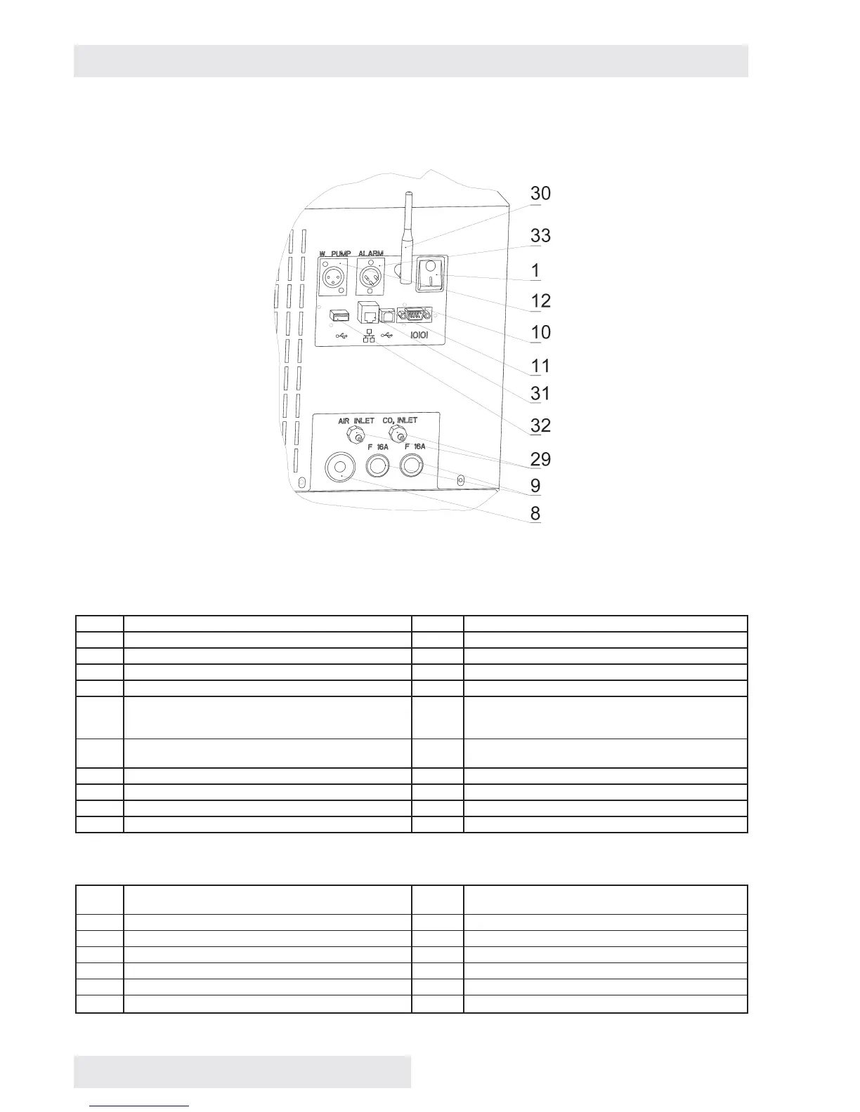
3.3 COMMUNICATION PANEL
Fig. 3
Standard version
1 Network push button 12 Pump connector
2 Control touch panel 13 Input of steam from steam generator
3 Plastic cover of control panel 14 Waste vessel with pump
4 Condenser 15 Waste water discharge
5 Compressor 16 Water inlet from reservoir
6 Cooling tube evaporator -
6a - cooling,
6b - freezing (RH regulation)
17 Distilled water reservoir
7 Heating bodies in heating space 18 Outlet of waste water from chamber and door to the
vessel
8 Network connection 19 Temperature sensor PT 100
9 Fuses T16A/1500 20 Relative humidity sensor
10 Connector RS232 21 Screens (2 pcs)
11 Connector USB device (USB B)
Optional equipment
22 Exposition lighting in the door (LED, fl uorescent
lamps)
29 Inlet of CO
2
(gas) and air (external)
23 Exposition lighting of racks ( LED, fl uorescent lamps) 30 Wifi antenna
24 Lighting sensor (VIS or UV) 31 LAN connector
25 Placement inside of switched socket 32 Connector USB HOST
26 Placement of inner bushing 33 Potential-free contact
27 Sensor of CO
2
(gas) 37 Outlet of steam prom pressure safety lock
28 Inlet of CO
2
(gas) to the chamber (internal)