Instructions for use
32 CLIMACELL EVO_np_en_1401_mmm_V1.01
Note:
- A condition for fi nishing a program in programs with light
exposition is the selected exposition (see Fig. 53).
- In case of the device not to be equipped with sensors for
light intensity measuring, there must be set the value of
VIS or UV light intensity according to 8.3.10.4.
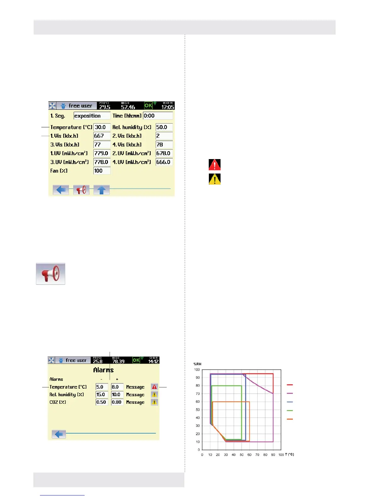
Fig. 57
(1) Required exposition conditions.
(2) Light exposition for individual racks.
8.4.4.2 ALARMY
Alarms warn the user that one of the regulated variables has
moved outside the pre-set limits. The temperature, relative
humidity and CO
2
concentration can be monitored (CO
2
is
an optional device accessory, see 6.14). How the device
acts when the alarm is triggered depends on the settings for
the button (3), fi g 58, and is the same as when a warning or
error occurs (see 8.3.3).
Fig. 58
(1)
(2)
(1) Monitored variable
- Alarms may be set for temperature, humidity and
CO
2
concentration
(2) Setting monitored limits
- See fi g. 55.
- With horizontal segments the system monitors
limits defi ned by positive and negative deviations
from the required variables – segments s2, s4, s6.
- Defi nition of monitored zone for ramps – segments
s3, s5.
- If 0 % is set for a positive and negative deviation,
the alarm is switched off - segment s1. The
temperature in the chamber is them monitored by
the safety thermostat only (8.4.2.1).
(3) Device action when an alarm occurs.
-
device acts as if a critical error has occurred.
-
device acts as if a warning has occurred.
Note:
If a certain variable needs to be quickly ramped up to
its target value in a segment (typically temperature or
humidity), when switching to the next (horizontal) segment,
there may be a slight overshoot above the required value.
This cannot be completely eliminated during regulation.
Therefore, in such cases we recommend setting the alarm
limits so that the tolerated band is not too narrow, or fi rst
testing out the alarm settings.
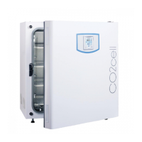
8.4.5 TEMPERATURE AND RELATIVE
HUMIDITY SETTING AND THEIR
LIMITATIONS
The mutual relation of operation temperature (T °C) and
operation relative humidity (RH %) when setting the
operation parameters of the case depending on additional
equipment is illustrated in the enclosed scheme.
Temperature and relative Humidity Setting
and Their Limitations
Fig. 59
(3)
(2)
(1)
CLIMACELL
Lighting – door
CO
2
Lighting – racks -
LED
Lighting – racks –
fl uorescent lamps