EasyManua.ls Logo

Mobotix D24M - Page 59

Mobotix D24M
148 pages
Print Icon
To Next Page IconTo Next Page
To Previous Page IconTo Previous Page
Loading...
ī˜˜ī˜œī˜’ī˜”ī˜–ī˜–
ī˜§ī˜•ī˜—ī˜ƒī˜¦ī™„ī™ī™ˆī™•ī™„ī˜ī˜°ī™„ī™‘ī™˜ī™„ī™ī˜ī˜ƒī˜¬ī˜±ī˜¶ī˜·ī˜¤ī˜Æī˜Æī˜¤ī˜·ī˜¬ī˜²ī˜±
ī©ī˜ƒī˜°ī˜²ī˜„ī˜²ī˜·ī˜¬ī˜»ī˜ƒī˜¤ī˜Ŗī˜ƒī˜ƒī”ī˜ƒī˜ƒī˜¶ī™ˆī™†ī™˜ī™•ī™Œī™—ī™œī˜ī˜¹ī™Œī™–ī™Œī™’ī™‘ī˜ī˜¶ī™œī™–ī™—ī™ˆī™ī™–ī˜ƒī˜ƒī”ī˜ƒī˜ƒī˜°ī™„ī™‡ī™ˆī˜ƒī™Œī™‘ī˜ƒī˜Ŗī™ˆī™•ī™ī™„ī™‘ī™œ
www.mobotix.com • sales@mobotix.com
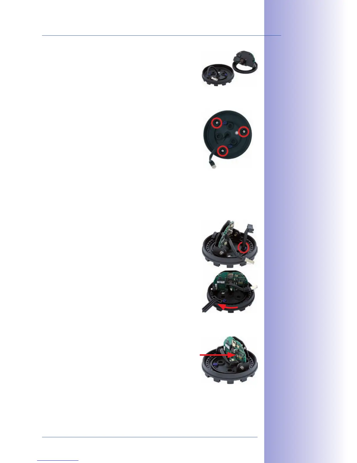
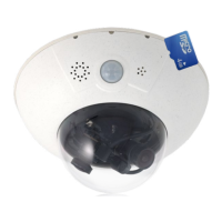
4. ī˜µī™ˆī™ī™’ī™™ī™ˆī˜ƒī™—ī™‹ī™ˆī˜ƒī™Œī™‘ī™—ī™ˆī™•ī™‘ī™„ī™ī˜ƒī™“ī™„ī™•ī™—ī˜ƒī™’ī™‰ī˜ƒī™—ī™‹ī™ˆī˜ƒī™†ī™„ī™ī™ˆī™•ī™„ with the lens
mount from the base of the camera.
5.
ī˜³ī™’ī™–ī™Œī™—ī™Œī™’ī™‘ī˜ƒī™—ī™‹ī™ˆī˜ƒī™…ī™„ī™–ī™ˆī˜ƒī™’ī™‰ī˜ƒī™—ī™‹ī™ˆī˜ƒī™†ī™„ī™ī™ˆī™•ī™„ī˜ƒī™‹ī™’ī™˜ī™–ī™Œī™‘ī™Šī˜ƒī™’ī™™ī™ˆī™•ī˜ƒī™—ī™‹ī™ˆī˜ƒī™‡ī™•ī™Œī™ī™ī™ˆī™‡ī˜ƒ
ī™‹ī™’ī™ī™ˆī™– and the prepared cable exit. Please make sure
that the camera base is relatively flush with the surface.
The network cable with connector should be flush with
the ceiling or wall as a result. Since the three holes for
the screws in the outer shell are factory sealed, they
must broken open, for example, using a 5mm drill bit.
6. ī˜·ī™Œī™Šī™‹ī™—ī™ˆī™‘ī˜ƒī™—ī™‹ī™ˆī˜ƒī™…ī™„ī™–ī™ˆī˜ƒī™’ī™‰ī˜ƒī™—ī™‹ī™ˆī˜ƒī™†ī™„ī™ī™ˆī™•ī™„ī˜ƒī™˜ī™–ī™Œī™‘ī™Šī˜ƒī™—ī™‹ī™ˆī˜ƒī™–ī™˜ī™“ī™“ī™ī™Œī™ˆī™‡ī˜ƒ
screws. Depending on the installation site, the screw
openings should be sealed shut (e.g. with silicon).
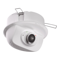
7. ī˜¬ī™‘ī™–ī™ˆī™•ī™—ī˜ƒ ī™—ī™‹ī™ˆī˜ƒ ī™Œī™‘ī™—ī™ˆī™•ī™‘ī™„ī™ī˜ƒ ī™“ī™„ī™•ī™—ī˜ƒī™’ī™‰ī˜ƒ ī™—ī™‹ī™ˆī˜ƒ ī™†ī™„ī™ī™ˆī™•ī™„ī˜ƒ ī™šī™Œī™—ī™‹ī˜ƒ ī™—ī™‹ī™ˆī˜ƒī™ī™ˆī™‘ī™–ī˜ƒ
ī™ī™’ī™˜ī™‘ī™—ī˜ƒī™Œī™‘ī™—ī™’ī˜ƒī™—ī™‹ī™ˆī˜ƒī™„ī™—ī™—ī™„ī™†ī™‹ī™ˆī™‡ī˜ƒī™’ī™˜ī™—ī™ˆī™•ī˜ƒī™–ī™‹ī™ˆī™ī™ and secure it by
turning the two blue clamps in a clockwise direction using
the supplied hook wrench or a screwdriver. This will pre-
vent the internal part of the camera from falling out before
it has been tightened into place.
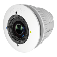
8. Now secure the internal part of the camera by turning
the toothed ring in a clockwise direction until you can still
turn the internal part of the camera without much force.
9. ī˜¦ī™’ī™‘ī™‘ī™ˆī™†ī™—ī˜ƒī™—ī™‹ī™ˆī˜ƒī™‘ī™ˆī™—ī™šī™’ī™•ī™Žī˜ƒī™†ī™„ī™…ī™ī™ˆī˜ƒto the network connector
of the camera.
10. Proceed to Section 2.11, Aiming And Adjusting The Lens.

Table of Contents

Related product manuals