www.mobotix.com • sales@mobotix.com
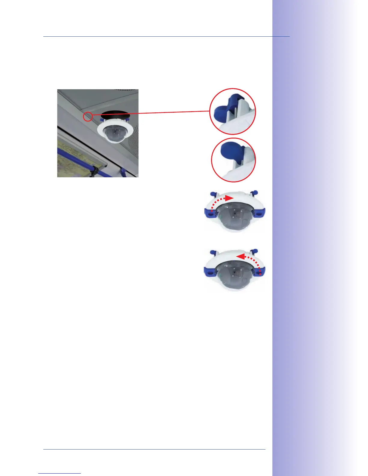
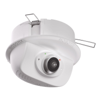
7. : Make sure that all winged
cams are retracted before placing the In-Ceiling Set with the camera into the hole.
Tightening the screws of the In-Ceiling Set extends the winged cams, thus firmly
holding the set in place.
8. : Use the two wrenches from
the In-Ceiling Set to place the ring on the set as shown
in the figure and turn the ring clockwise until it stops.
The two wrenches from the are also used
for . Insert them as shown and turn the ring
counter-clockwise. Loosen the screws of the In-Ceiling
Set; this will automatically retract the winged cams. You
can now remove the In-Ceiling Set, with the camera still
attached, from the ceiling.
9. Proceed to Section 2.11, Aiming And Adjusting The Lens.
The blue winged cams
(see left) automatically
secure the In-Ceiling
Set in the ceiling when
tightening the screws
Removing the decora-
tive ring:
turn counter-clockwise
– only relevant when
completely remov-
ing the camera
Installing the decora-
tive ring:
turn clockwise