Engineering
24
12/03 AWB-C27-1293GB
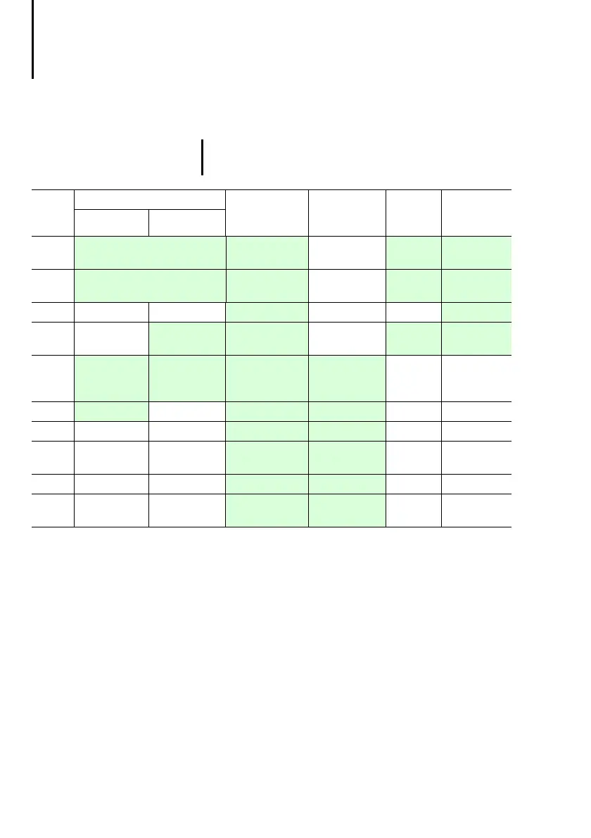
Table 4: Assignment of the adapter extensions in the MI4
hand-held
1) The assignment of the AUX PORT depends on the
connected interface module. Currently, these are the
interface modules for Suconet K and Siemens MPI
(electrically isolated). For further information, please read
the next section.
Delivery state
As supplied, the MI4 hand-held is prewired for
Suconet K and Sucom A communication. The unit is
supplied with a 5 m long cable. The respective
communication module must be ordered separately!
)
The green fields indicate the adapter number
used for each connection.
Plug
No.
CN1 (AUX PORT)
1)
CN2
(PC/PRINTER
PORT)
CN3
(PLC PORT)
CN4
Power
CN5
Additional
signals
Suconet K MPI
1
GND (brown/pink) CHA+ Reserved +24 V DC
(red)
DM Right
(blue)
2
+5 V output (max. 100 mA)
(orange/pink)
CHA– Reserved Common
(black)
DM Right
(blue-black)
3
CHB+ Reserved Reserved DM Left (cyan)
4
A CHB– Reserved PE DM Left
(cyan-black)
5
A (yellow/pink) B (yellow/pink) + 5 V output
(max. 100 mA)
(green)
+ 5 V output
(max. 100 mA)
(red)
––
6
B (green/pink) GND (grey) GND (black) – –
7
RxD (orange) RxD (blue/red) – –
8
CTS (brown) CTS (purple/
red)
––
9
TxD (white) TxD (blue/black) – –
10
RTS (pink) RTS (purple/
black)
––