-12-
Revision 7/F3512
© Moffat Ltd, January 2005
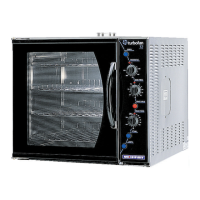
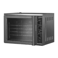
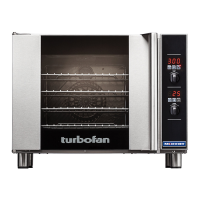
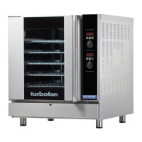
E35 Turbofan Ovens
This allows only the oven lights to be operational
if the oven door is opened.
Thermostat Control
Heating of the oven is controlled by an
electronic thermostat control, comprising of a
potentiometer dial and knob on the control panel,
a temperature sensing probe (thermistor type) in
the oven chamber, and the thermostat control
board behind the control panel. Power to the
electronic thermostat is supplied through an
over-temperature/hi limit thermostat. Accordingly
a failure of the electronic thermostat control
causing a temperature over-run will result in the
over-temperature thermostat switching and
removing power from the heating control circuit.
The over-temperature thermostat is able to be
manually reset, however a serviceman is required
to perform this function, as removal of the R/H
service panel is required to access this safety
protection device.
The electronic thermostat when set to a
temperature will illuminate the heating neon
indicator on the control panel whenever the oven
heating elements are on. When the indicator
neon goes out, the oven is up to the set
temperature.
Heating / Elements
The electronic thermostat when requiring heating
of the oven, switches power to the heating
contactor (referred to as C1 contactor in this
manual). The heating contactor closes to supply
power through to the heating elements in the
oven. In all ovens all 3 poles of the contactor are
used to supply L1, L2, and L3 phase circuits to
the 3 heating elements on each side of the oven
fan motor.
On 3 Phase + Neutral supply models, all 6
elements are looped to neutral, and the 3 Phase
power to the elements is to each set of three
elements in parallel connection. Hence each of
the elements is supplied with the Phase to
Neutral voltage.
On 3 Phase supply models (no neutral), the set
of three elements each of the fan motor are
connected in Delta configuration, which each
element being supplied the Phase to Phase
voltage.
On 1 Phase + Neutral supply models, all 6
elements are looped to neutral, and the 1 Phase
power to the elements is split into three poles at
the main circuit breakers on the oven, then feed
through the three poles of the heating contactor,
from where each pole is connected to two of the
six elements in parallel. Hence each of the
elements is supplied with the Phase to Neutral
voltage.
The heating elements are rated at 2000 Watts
each, therefore providing a total of 12000 Watts
or 12kW of heating.
In some cases special heating kilowatts may be
supplied to special request, so always check
rating plate information on the unit if in doubt.
The heating contactor cycles ON/OFF as
controlled by the thermostat to maintain set oven
temperature.
Fan / Motor
The E35 Turbofan ovens use a dual speed,
bi-directional oven fan circulation system, in order
to provide even heat distribution through the
oven, and fan speed control to suit different
product types.
To provide both dual fan speed and bi-direction, a
motor of 4pole/8pole configuration is used.
Fan / Motor Direction
The direction change is made by swapping two
phases to the motor through the motor contactors
C2 and C3. In one direction L1, L2, and L3 are
switched through motor contactor C2 with motor
contactor C3 open. In the alternate direction,
motor contactor C2 is open, and C3 is closed. L1
and L2 are reversed on the C3 contactor
connections. Motor contactors C2 and C3 are
mechanically interlocked (interlock fitted to rear of
contactors) to prevent any switching overlap.
Motor direction change is automatic, and the
duration of the direction cycle is factory set.
Additionally, a dwell period between at each
change of direction occurs to allow the motor to
restart in the opposite direction only after the
motor rotation has slowed down. This is
necessary to avoid motor overheating due to the
high current load that would be required to
change direction instantaneously.
Each direction cycle is 90 seconds long, at the
beginning of which is a preset 10 second dwell/
delay. As the dwell is at the beginning of the cy-
cle, the fan always has a 10 second start delay
when the oven is first turned on, or when the door
is closed after opening.
The direction control timing is provided from three
electronic timers mounted below the motor
contactors on the electrical switchgear panel of
the oven. Timer T1 controls the direction cycle
time, timer T3 controls the dwell for one direction,
and timer T5 controls the dwell for the opposite
direction.