-65-
Revision 7/F3512
© Moffat Ltd, January 2005
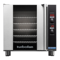
E35 Turbofan Ovens
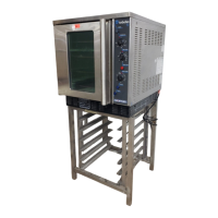
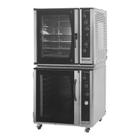
APPENDIX B. STAND MOUNTING INSTRUCTIONS
A. UNPACKING
Check stand includes correct parts and correct
quantities for the stand purchased as listed.
A26C has ‘Castor Stem Sockets’ in Stand
Frames, not feet.
ITEM DESCRIPTION Qty
A Stand frame front 1
(Nutserts one side only)
B Stand frame rear 1
(Nutserts both sides)
D Rack 2
E Screw -
3
/
4
"x
1
/
4
" BSW hex hd 8
E Washer -
1
/
4
" Spring 8
E Washer -
1
/
4
” Flat 8
F Screw - 2
1
/
4
"x
3
/
4
" hex hd 4
Castor (A26C only) 2
Castor braking (A26C only) 2
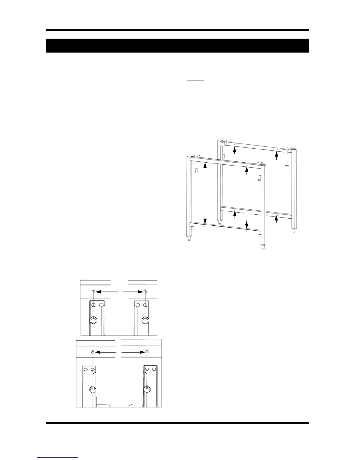
B. ASSEMBLY (diagram on reverse side)
Stand
1) Place front stand frame (A) on working
surface with threaded holes and oven
supports face up.
2) Fit both racks (D) to the stand frames (A).
Take care which holes are used to secure the
racks as inside holes in rack uprights (D) are
used for 18” (460mm) wide trays, and outside
holes are used for 16” (405mm) wide trays.
3) Turn assembly upright.
5) A26C only. Insert castors into Stand Frames,
ensure 2 braking castors are in front frame.
(Front frame has nutserts in one face only)
Oven - mounting on stand
6) Remove feet from oven (if fitted).
7) Oven should be place onto stand with
threaded holes in ovens foot plates lining up
with holes in oven supports on stand.
8) Secure oven using screws (F).
9) A26 only. Adjust stand feet to level the oven.
10) A26C only. Ensure braking castors are in
front frame.
4) Fit the other stand frame (B) with screws and
washers (E).
NOTE:
Take care which way around the frame
is. For 26” oven have the oven supports
facing the racks, for 30” oven have the
supports (C) facing away from racks (refer
figure B.2).
Take care which holes are used to secure the
racks, as in 2 above.
16” (405m
m) wide
trays
18” (460mm)
wide trays
D
D
G
G
Figure B.2
B
F
C
A
G
G
G
G
G
G
G
G
R
E
A
R
R
a
c
k
m
o
u
n
t
i
n
g
h
o
l
e
s
b
o
t
h
s
i
d
e
s
F
R
O
N
T
R
a
c
k
m
o
u
n
t
i
n
g
h
o
l
e
s
o
n
e
s
i
d
e
o
n
l
y
Figure B.1