-34-
Revision 7/F3512
© Moffat Ltd, January 2005
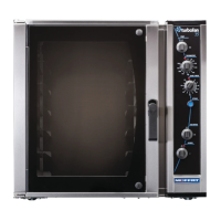
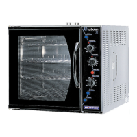
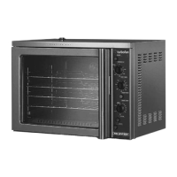
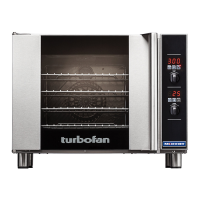
E35 Turbofan Ovens
All the timers have a dial on the front that adjusts
the time the timer switches for when control
energised. All the timers have an LED on the
front that flashes when the timer is switched.
T1 Fan Cycle Timer
This timer switches power between the clockwise
and anti-clockwise fan direction circuits, the time
set is the duration on each fan direction.
Factory set to 1
1
/
2
minute.
Refer to Appendix C for timer settings.
T2 & T4 Steam Timers (2)
These should be set the same and determine the
duration of the steam, one for clockwise fan
circuit and one for anti-clockwise fan circuit. If the
steam cycle is too long water will condense on
the product and oven chamber, and oven may
cool too much - it is usually better to have
multiple cycles than a long cycle.
Factory set to 10 seconds.
Refer to Appendix C for timer settings.
Steam injection activated
Steam injection activated
Steam injection activated
T3 & T5 Dwell Timers (2)
Once again these should be set the same, this is
the delay time between fan directions and after
steaming, when no power is applied to the fan
motor. One is for the clockwise fan circuit and
one is for the anti-clockwise fan circuit.
Factory set to 10 seconds.
Refer to Appendix C for timer settings.
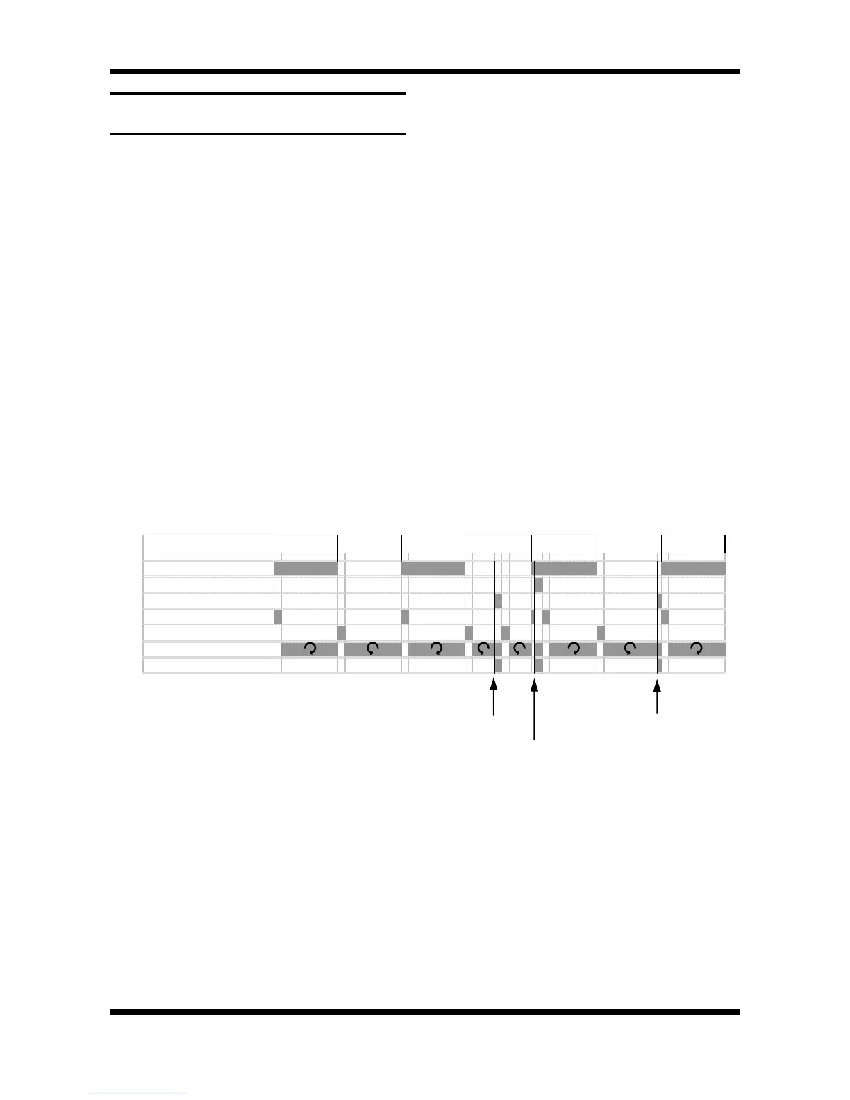
Figure 6.4.5 shows the function of the timers on a
time line. The grey areas are when a timer is
switched (LED flashing) or where fan is rotating /
steam injecting. The dark lines show when the
steam button has been pressed, the first is most
common while the next two show the effect of
steaming at the beginning or end of a direction
cycle. Priority (power flow) is top to bottom on
the chart (cycle timer effects all others)
6.4.5 FAN & STEAM TIMER OPERATION /
ADJUSTMENT
Figure 6.4.5
1
1
/
2
min 1
1
/
2
min 1
1
/
2
min 1
1
/
2
min 1
1
/
2
min 1
1
/
2
min 1 1/2 min
T1 Cycle timer
T2 Steam Clockwise
T4 Steam Anticlockwise
T3 Dwell Clockwise
T5 Dwell Anticlockwise
Fan rotation
Steaming