-29-
Revision 7/F3512
© Moffat Ltd, January 2005
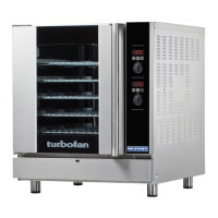
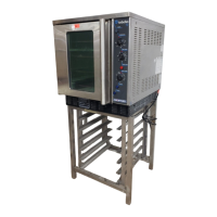
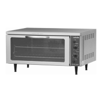
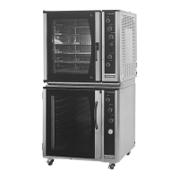
E35 Turbofan Ovens
Two Screws
Switch Screws
(2)
Bracket
Screws (4)
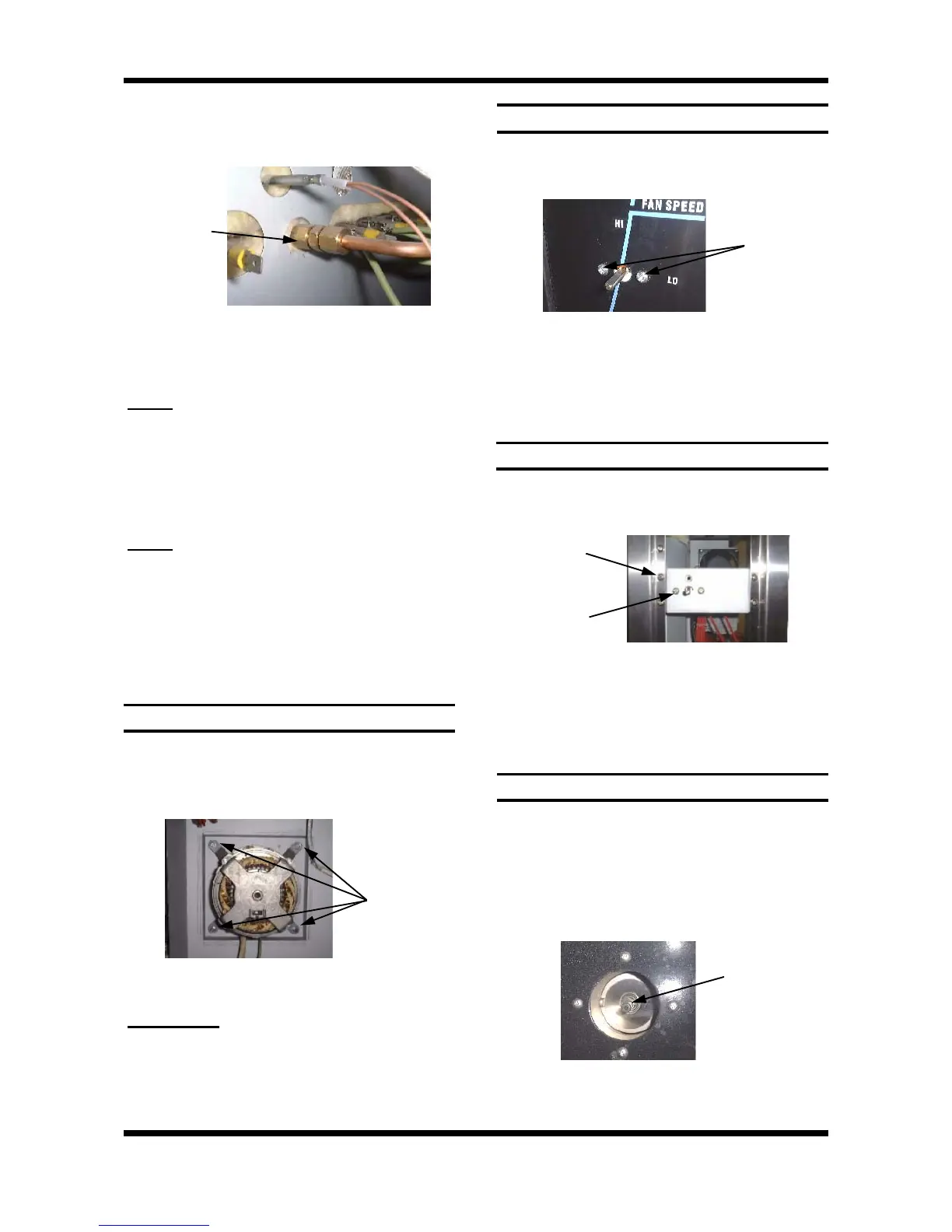
6.3.24 VENT / ‘OVER-PRESSURE’ VENT
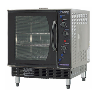
6.3.23 VENT SWITCH
6.3.21 MOTOR
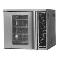
6.3.22 FAN SPEED SWITCH
1) Pull knob off front of switch.
2) Open control panel (refer 6.2.1) and undo 2
screws securing switch.
3) Transfer wires to new switch. Pull 2nd switch
off and transfer to new switch.
4) Withdraw old switch and insert new switch,
securing with screws.
Figure 6.3.34
1) Remove fan (refer 6.3.19).
2) Undo the 4 bolts holding the motor in place
(from the outside) and remove motor.
1) With control panel open (refer 6.2.1) remove
the four screws securing bracket and two
screws securing switch.
1) Remove vent switch (refer 6.3.23) and Baffle
(refer 6.2.3).
2) Rotate vent shaft 180° such that the spring is
facing into the oven.
3) With 3mm Allen key remove Allen screw
holding spring and vent assembly (inside top
back RHS of oven).
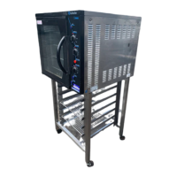
2) Undo the steam line compression fitting on
the outside of the oven nearest the oven.
Steam Line
Compression
Fitting
Figure 6.3.32
3) Pull assembly (steam nozzle etc) into the
oven (without damaging probe lines) and
support clear of the fan.
NOTE:
Removal of the probe and mounting plate
will require breaking of the silicone sealant.
4) Undo the bolt in the centre of the fan (use fan
blades and heat deflector to steady).
5) Use a gear puller if necessary to remove the
fan from the tapered shaft.
6) Replace and re-assemble in reverse order.
NOTE:
Ensure probe mounting plate has RTV
silicone sealant applied to sealing face to
ensure a leak proof assembly. Remove ex-
cess sealant after tightening securing screws.
Four Bolts
Figure 6.3.33
Figure 6.3.35
Allen Screw
Figure 6.3.36
4) Internal vent pressure relief and vent shaft
can now be removed and replaced.
3) Disconnect motor leads.
IMPORTANT:
Note wire colour and terminal
connections.
4) Replace and reassemble in reverse order.
Ensure wire leads are re-connected to correct
contactor terminals.
2) Remove bracket (twist to clear frame and pull
forward), and switch (pull forward).
3) Transfer wires to the new switch and
re-assemble in reverse order.