-27-
Revision 7/F3512
© Moffat Ltd, January 2005
E35 Turbofan Ovens
Prise out switch
locking tab
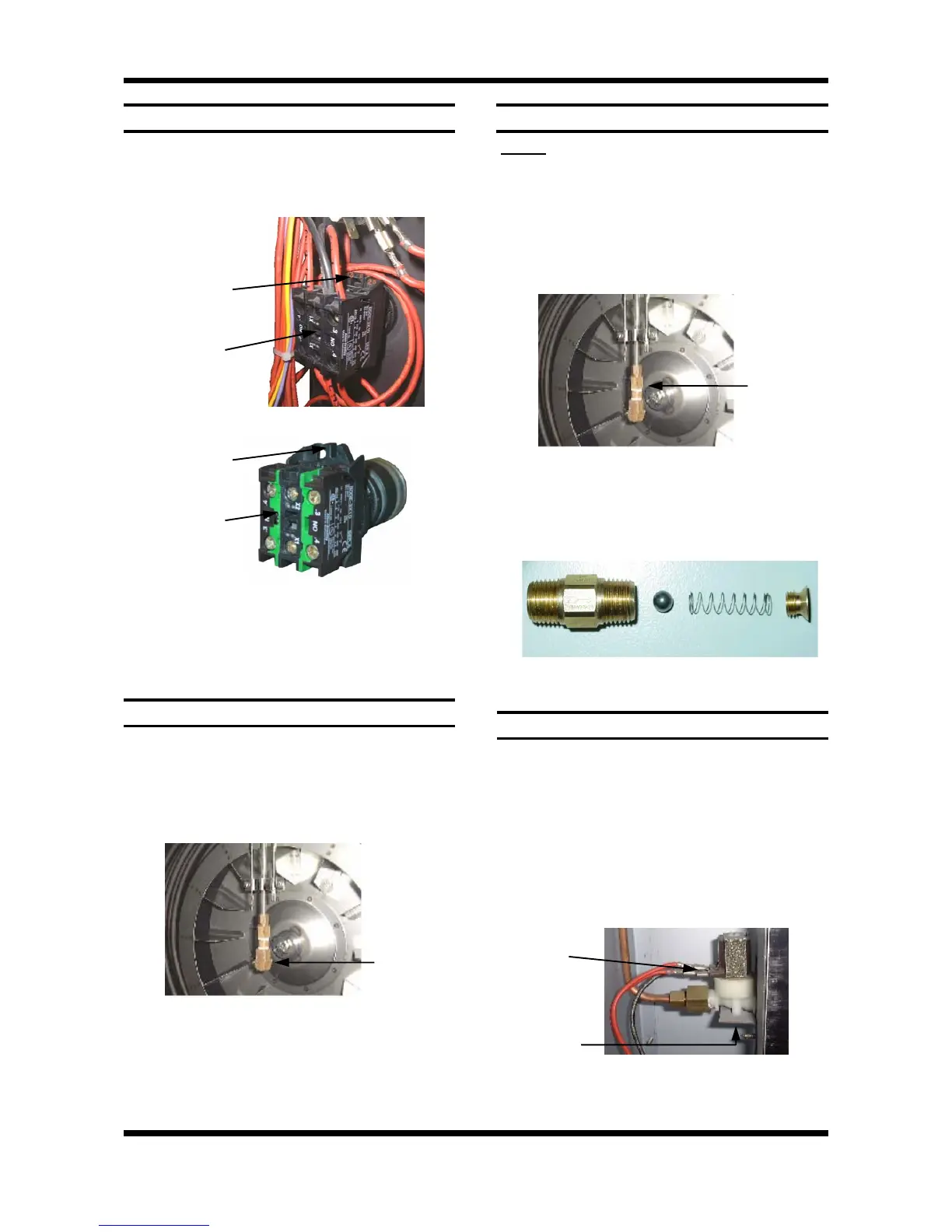
6.3.14 SPRAY NOZZLE
1) Remove the fan baffle (refer 6.2.3).
2) Unscrew the spray nozzle with
9
/
16
” and
5
/
8
”
spanners.
3) Clean or replace as required, ensuring
debris free on re-assembly.
Spray
Nozzle
Figure 6.3.22
6.3.13 STEAM SWITCH
1) Open control panel (refer 6.2.1).
2) Prise out or rotate the switch locking tab with
a small screwdriver, and withdraw the steam
switch assembly.
Figure 6.3.20
3) Transfer wires to new steam switch, and
re-assemble in reverse order.
Steam switch
Rotate switch
locking tab
Steam switch
Figure 6.3.21
6.3.15 CHECK VALVE - UP TO S/N 261984
NOTE: If the check valve becomes blocked or
corroded, the recommended course of action is to
remove the internal parts of the valve, as it is not
required for operation of the oven. The procedure
for this is given below.
1) Remove the spray nozzle (refer 6.3.14).
2) Remove the check valve with
1
/
2
” and
5
/
8
”
spanners.
Figure 6.3.24
Ball Spring
3) Dismantle the valve as illustrated, and discard
the ball and spring from the valve.
4) Reassemble the valve (without the ball and
spring) and refit to the unit.
Check
Valve
6.3.16 WATER SOLENOID
1) Ensure water supply is turned off.
2) With the R/H service panel removed (refer
6.2.2) remove the wires from the solenoid.
3) Undo the compression fitting on the output
side of the solenoid (
1
/
2
” spanner).
4) Remove the hose fitting, inlet side, and
adapter (
13
/
16
”), outlet side.
5) Remove two screws (up under bracket) and
extract.
Solenoid
Wires
Two Screws
Figure 6.3.25
6) Secure new solenoid with screws, and
re-assemble.
Figure 6.3.23