-26-
Revision 7/F3512
© Moffat Ltd, January 2005
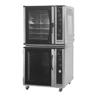
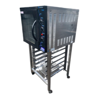
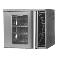
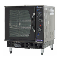
E35 Turbofan Ovens
Two Screws
6.3.10 CONTACTORS / TIMERS ETC
1) With R/H service panel removed (refer 6.2.2),
remove the din rail mounted component.
2) Install the new component onto the din rail.
3) Transfer the wires from old component to new
one.
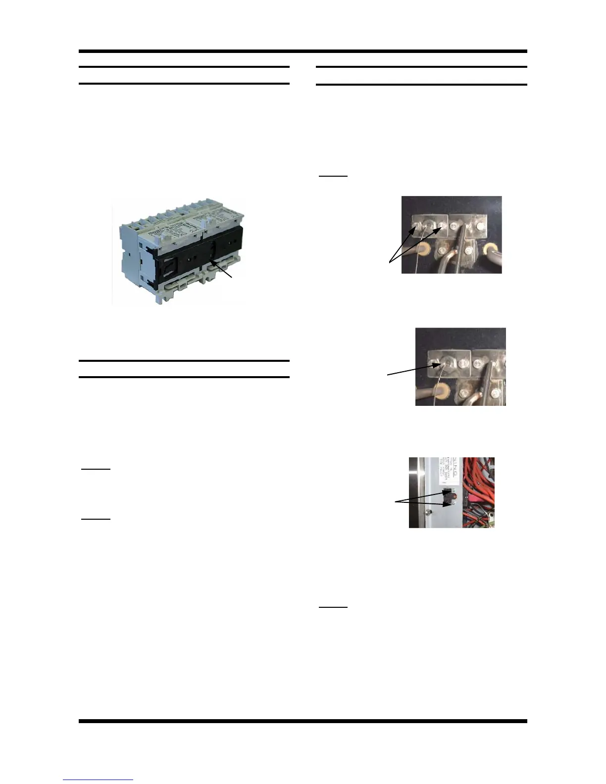
4) On contactors C2-C3, and C5-C6, ensure that
mechanical interlock (part number 020769) is
fitted as illustrated below.
6.3.12 OVER-TEMP THERMOSTAT
1) Remove service panel (refer 6.2.2) and baffle
(refer 6.2.3).
2) Remove bracket on steam line inside oven
cavity by undoing the 2 screws (figure .3.15).
3) Undo the 2 bolts on the flange where the
probe enters the oven (inside oven).
NOTE:
Removal of the probe and mounting plate
will require breaking of the silicone sealant.
5) Undo the 2 screws holding the over-temp and
remove over-temp.
Figure 6.3.19
6) Transfer wires from old over-temp thermostat
to the new one.
7) Install the new over-temp and probe in the
reverse order of above.
NOTE:
Ensure probe mounting plate has RTV
silicone sealant applied to sealing face to
ensure a leak proof assembly. Remove
excess sealant after tightening securing
screws.
6.3.11 ELEMENTS
1) With service panel and baffle removed (refer
6.2.2 & 6.2.3) remove the wires from the
element.
2) With the use of an
11
/
16
” tube spanner, undo
the nuts on the outside at the element ends.
3) Pull element into oven and remove.
NOTE:
When replacing or refitting elements
ensure that the fibre sealing washers are
used.
Element Resistances
NOTE:
Element must be disconnected for
testing. Resistances are given at room
temperature.
208-220V 24.2 Ω
230-240V 28.8 Ω
Figure 6.3.16
Interlock fitted to
rear of contactors
4) Undo gland nut on bracket and extract the
probe from the bracket.
Two Bolts
Figure 6.3.17
Gland Nut
Figure 6.3.18