-14-
Revision 7/F3512
© Moffat Ltd, January 2005
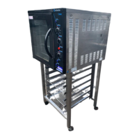
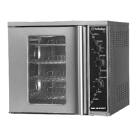
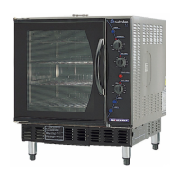
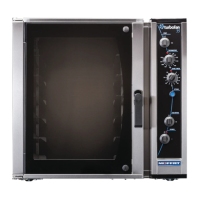
E35 Turbofan Ovens
the hot elements, which is supported by the hot
air of the oven also turning the water droplets into
steam.
The steam is initiated by depressing the Steam
switch on the control panel. When depressed the
steam switch provides power one of two Steam
timers which are preset to 10 seconds steam
cycle duration. These Steam timers are T2 and
T4.
T2 is associated with fan dwell timer T3 and is
used when steam is required during the fan
direction cycle that uses the T3 dwell timer.
T4 is associated with fan dwell timer T5 and is
used when steam is required during the fan
direction cycle that uses the T5 dwell timer.
This ensures that steam can be used in either fan
direction cycle, and additionally allows the fan to
be turned on as soon as steam is activated, even
if the fan was in a direction change dwell.
Ensuring that the fan is running when steam is
required is necessary to atomise the water
droplets by the mechanical action of the fan, and
by the fan throwing the water across the
elements.
The Steam switch on the control panel only
needs to be depressed momentarily as the
duration of the steam injection is automatically
timed by the steam timers. The Steam switch will
illuminate for the duration of the steam injection to
provide a visual confirmation of the steaming
process. The light in the steam switch is
independent of the switch contacts and is
powered by the electrical circuit to the water
solenoid valve. Therefore the switch is
illuminated for as long as the water solenoid is
open: 10 seconds.
Summary of Components
The electrical switchgear (not user controls)
components are summarised as follows:
C1 Heating contactor
Switches elements ON/OFF
C2 Motor direction contactor
Phases switched in line
C3 Motor direction contactor
Phases L1 and L2 swapped on 3 phase
models
Run capacitor swapped from L1 to
Neutral on 1 phase models
C4 Motor speed contactor
HI speed
C5 Motor speed contactor
LO speed
C6 Motor speed contactor
HI speed (changes motor from 8 pole
to 4 pole)
T1 Fan cycle timer
Direction cycle
T2 Steam timer
For T3 dwell direction
T3 Fan dwell timer
Alternate direction (always initial
direction dwell)
T4 Steam timer
For T5 dwell direction
T5 Fan dwell timer
Alternate direction (always 2
nd
direction
dwell)
C7 Motor start capacitor contactor.
(Single phase models only)
T6 Motor start capacitor timer
(Single phase models only)
Motor contactor interlocks fitted to C2+C3
(mounted on rear on contactors)
Motor contactor interlocks fitted to C5+C6
(mounted on rear on contactors)
The following Troubleshooting Guide should be
used to identify any incorrect oven operation. On
correct identification of the operating fault the
Troubleshooting guide will make reference to the
corrective action required, or refer to the Fault
Diagnosis section and/or Service section to assist
in correction of the fault.