SST-DN4-PCU Hardware Reference Guide
1.5.1 CAN Connector
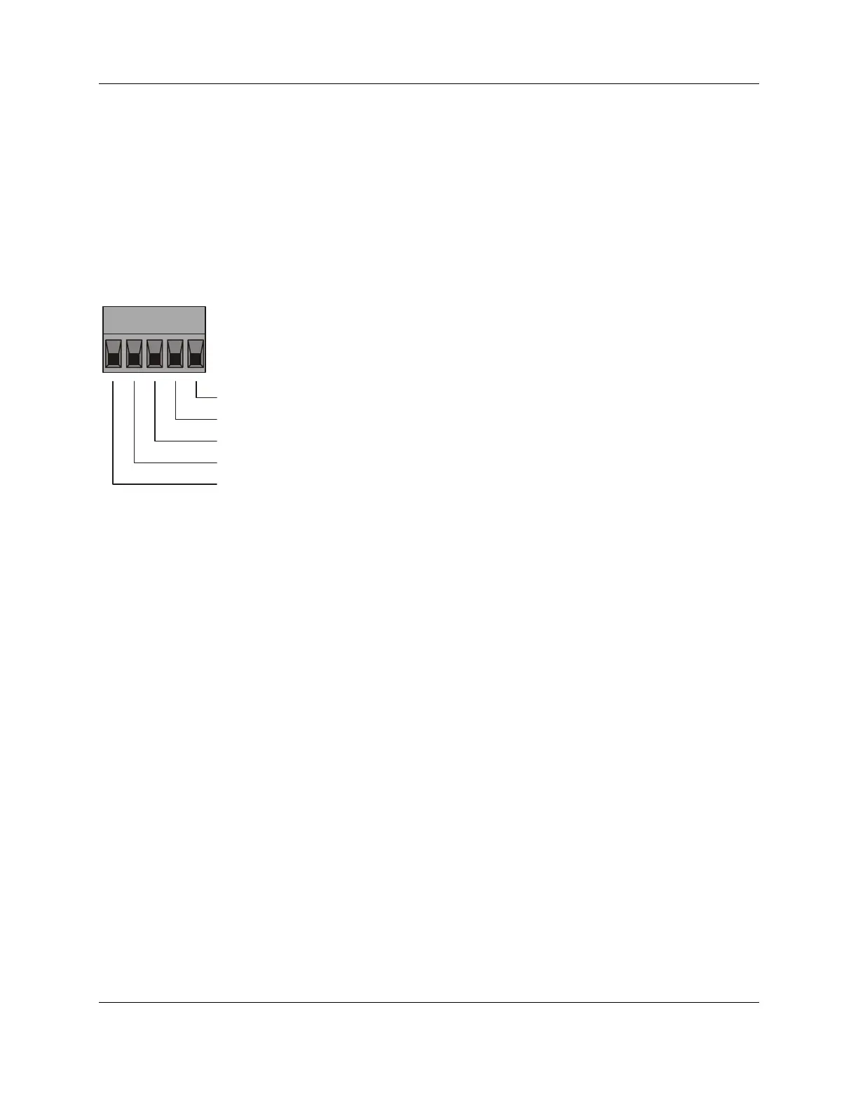
The 5-pin connector is a standard removable connector that conforms to the standard DeviceNet
pinout. Pin numbers, names, and color codes are identified in the figure below.
Figure 2: 5-Pin CAN Connector
12
345
CANH
V+
CANL
V-
SHIELD
Pin Name: DeviceNet
TM
Color Code:
White
Red
Blue
Black
Bare
1.5.1.1 V+, V-
These terminals provide power to the isolated section of the network interface, and must be
connected in order for the card to function. On DeviceNet networks, they connect directly to the
red (V+) and black (V-) wires of the DeviceNet cable. On non-powered CAN networks, they
must be connected to an external 11-24VDC supply.
16 Card Overview
©2009 Molex Inc.Automation & Electrical Products, Integrated Products Division
Document Edition: 1.0, Document #: 715-0101, Template Edition: 1.1, Template #: QMS-06-045
Use, duplication or disclosure of this document or any of the information contained herein is subject to the restrictions on page ii of this document.