05/06
•
53
ROUTINE MAINTENANCE
MILL BEARING GREASING INSTRUCTIONS
WARNING: To ensure that the drive
does not start unexpectedly, turn off
power source and lockout or tag out
power source before proceeding.
INSPECTION
Inspect drum shaft to ensure that the shaft is
smooth, straight and clean.
Inspect bearing for contamination. Do not
allow bearing to be exposed to any dirt or
moisture. Do not remove slushing com-
pound, since it acts as both a protectant and
lubricant and is also compatible with stan-
dard greases.
NOTE: Housing caps and bases are not
interchangeable. They must be reinstalled
with mating half. Install non-expansion
bearing rst (located on the drive side of the
drum.)
Apply a light coating of oil or other
rust inhibitor to the adapter area of the
shaft.
Measure the internal clearance of the
bearing before mounting. Place the
bearing in an upright position. Seat
the inner ring and roller elements by
pressing down rmly on the inner ring
bore while rotating the inner ring a few
times. Position the roller assemblies so
that a roller is at the top most position
on both sides. Press these top rollers
inward ensuring contact with center
guide ange (above 6 1/2” only.) Using
a feeler gauge, measure the clearance
for both sides by inserting as far as
possible and sliding over top of roller.
Write down the measured clearance for
use in step 3D.
NOTE: Do not rotate bearing when
moving feeler between roller and outer
ring.
Install the bearing parts in the following
sequence:
1.
2.
3.
NOTE: Bearing can only be correctly in-
stalled one way.
A. Seal Ring - Install a seal ring on shaft.
B. Adapter - Slide adapter onto the shaft,
threaded end outboard to the approximate
location of the bearing. Apply light coating of
oil to sleeve O.D.
C. Bearing - Install bearing on adapter
sleeve, large end of tapered bore rst. Lo-
cate bearing in proper position on shaft.
D. Lockwasher and Locknut - Install the
lockwasher (8” and smaller sizes only) on
the adapter with inner prong located in the
slot and toward the bearing. Install lock nut,
chamfered face toward bearing. Install non
expansion ring on drive side of bearing.
(CAUTION: Do not use a non expansion
ring in idler bearing.)
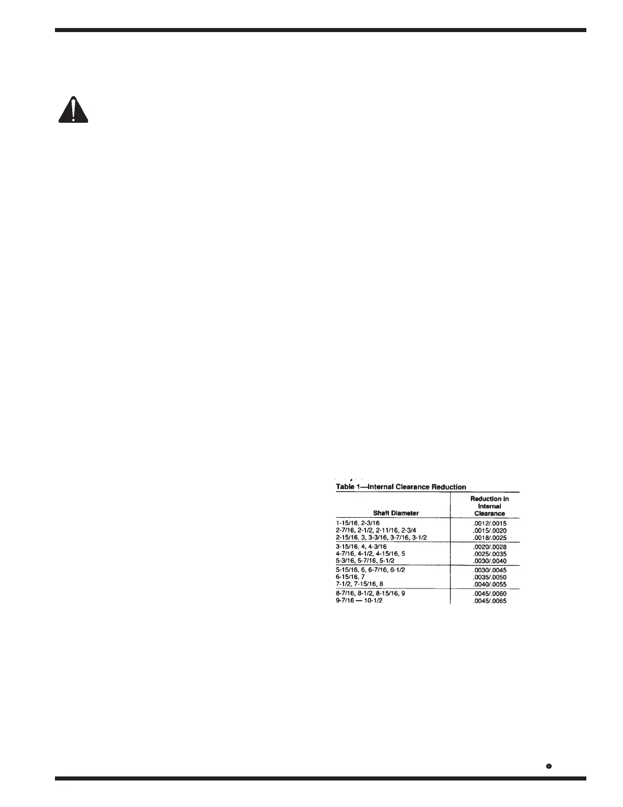
4” shaft and smaller - Tighten locknut us-
ing spanner wrench and hammer until clear-
ance noted in step 2 is reduced by amount
shown in Table 1. During this step, shaft
should be supported so all weight is off the
bearing.