FIG26.1
1.Beforeremovingthebladeassembly,ensurethatthelowerblade/anvilis
at‘topdeadcentre’,ie.PushButton3hasnotbeenpressed.Switchthemachineoff.
2.Removethedeliveryunitandliftthetopguard.
NOT
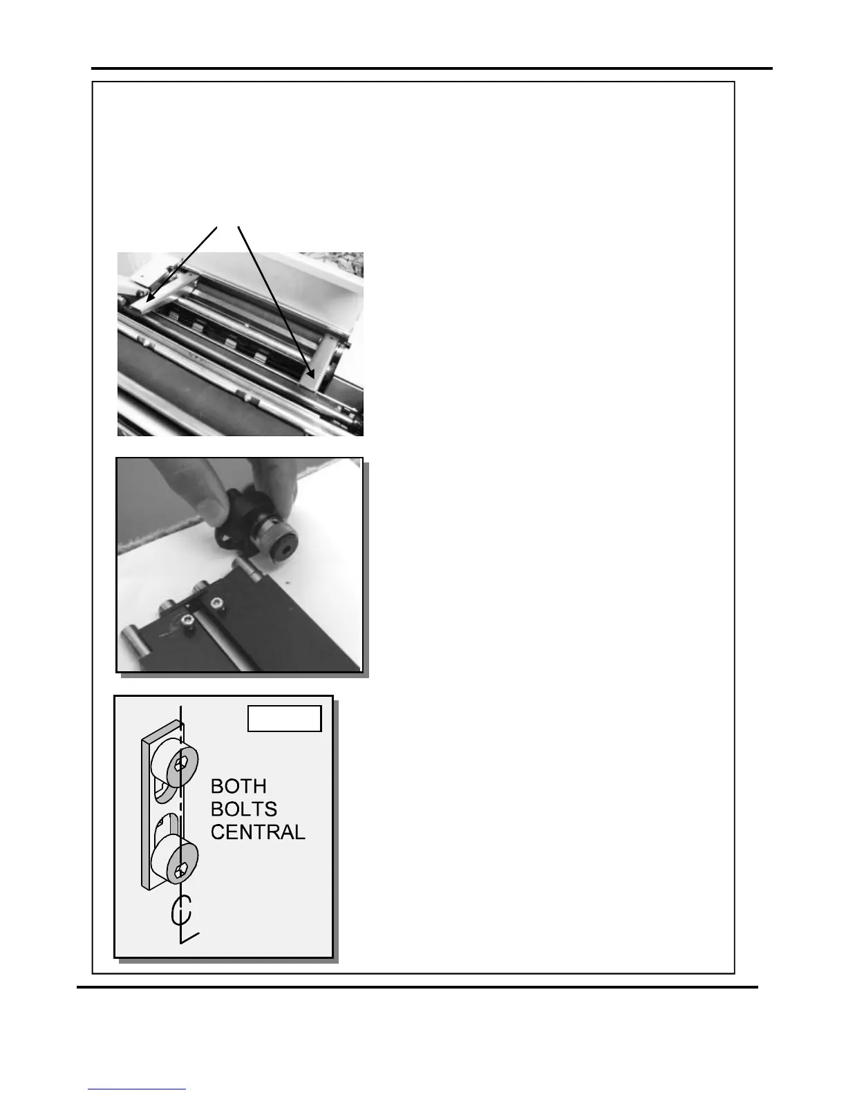
3.Usinga6mmallenkey,loosenthesocket
headscrewslocatedinsidetheblade
adjustmentcams.Removethescrewsand
thebladeadjustmentcams.
4.Insertthebladeextractortools(70-055-01&
70-055-02)
5.Slidethebladeassemblyoutofthecreasing
unitandlayitonaflatsurface.
6.Slidetheadjustmentlinksawayfromthe
dowelslocatedintheendsoftheblades/
anvilsasshowninthephotograph(left).
7.Placethenewbladesetintoposition.
Checkthattheeccentricshoulderboltson
thelinkplateshavebeenpositionedas
showninfig26.1.
8.(Upperblade/anvilonly)
Slidetheadjustmentlinksontothedowels.
intotheholesintheadjustment
links,asshown.Pushdownwardsonthe
handlesofthebladeextractortoolsto
releasethebladeassemblyfromthepower
links.
9.Slidethenewbladesetintotheslotsofthe
creasingunitasshowninfig.27.1.
Locatethebladeextractortoolsintotheholesin
theadjustmentlinksasshown.Pullthehandles
ofthebladeextractortoolsupwardstoengage
thebladeassemblybackintothepowerlinks.
10.Setthecamgraphicsforbothendsoftheblade/
anviltotheirlowestpointonthescale(ie.When
themarkonthescalereachesthemarkoncam
holder)Fastenthesocketheadscrewsonthe
adjustmentcamsuntiltheyaretight.
ReplacingBladeSets
BladeExtractorTools
Page27SYSTEM