MoTeC C125 Track Kits 13
• Display of sensor values
• Driver analysis
• Engine performance measurement
• Data analysis using MoTeC’s i2 software
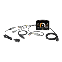
Kit contents:
• 18029 – C125 COLOUR DISPLAY LOGGER
• 29618 – C125 Logging upgrade 120MB
• 61260 – C125 ACCESSORY KIT containing:
o 41304 – GPS L10 10Hz
o 61221 – TWO BUTTON LOOM
o 61225 – NETWORK CABLE RJ45 1.5 METRE
o 62204 – C125 RACE LOOM TERMINATED
Installing the C125 Terminated Loom
The C125 has an optional terminated loom that is pre-configured to get the
most out of your Display Logger. This loom plugs directly into the back of the
C125, and has labelled wires for each of the parts that come with the Race
Kit. The loom has these connections:
• Power - Connect to a 12 - 32 V power source and ground with a 5
ampere fuse. When using the C125 Race kits, use the cigarette
lighter adapter.
• GPS - Ensure that you connect a compatible 5 V GPS unit only to the
lead labelled “GPS”. Plugging a GPS into the Accessories lead will
damage the GPS.
• Buttons - Plug in the button loom as supplied with the kit for Mode,
Alarm Acknowledge and Next Line functionality.
• Accessories – Use
this lead to connect a MoTeC CAN based
product to the C125, such as LTC, expander, HD-VCS
• ECU - ECU communications are sent to the C125 via this connector.
Terminated looms are available for OBD-II, M84, MoTeC ‘Hundred
Series’ ECUs and RS232 (M4, M48 and other brands).
• Ethernet - For communications between your Dash and a PC for
configuration.
 Loading...