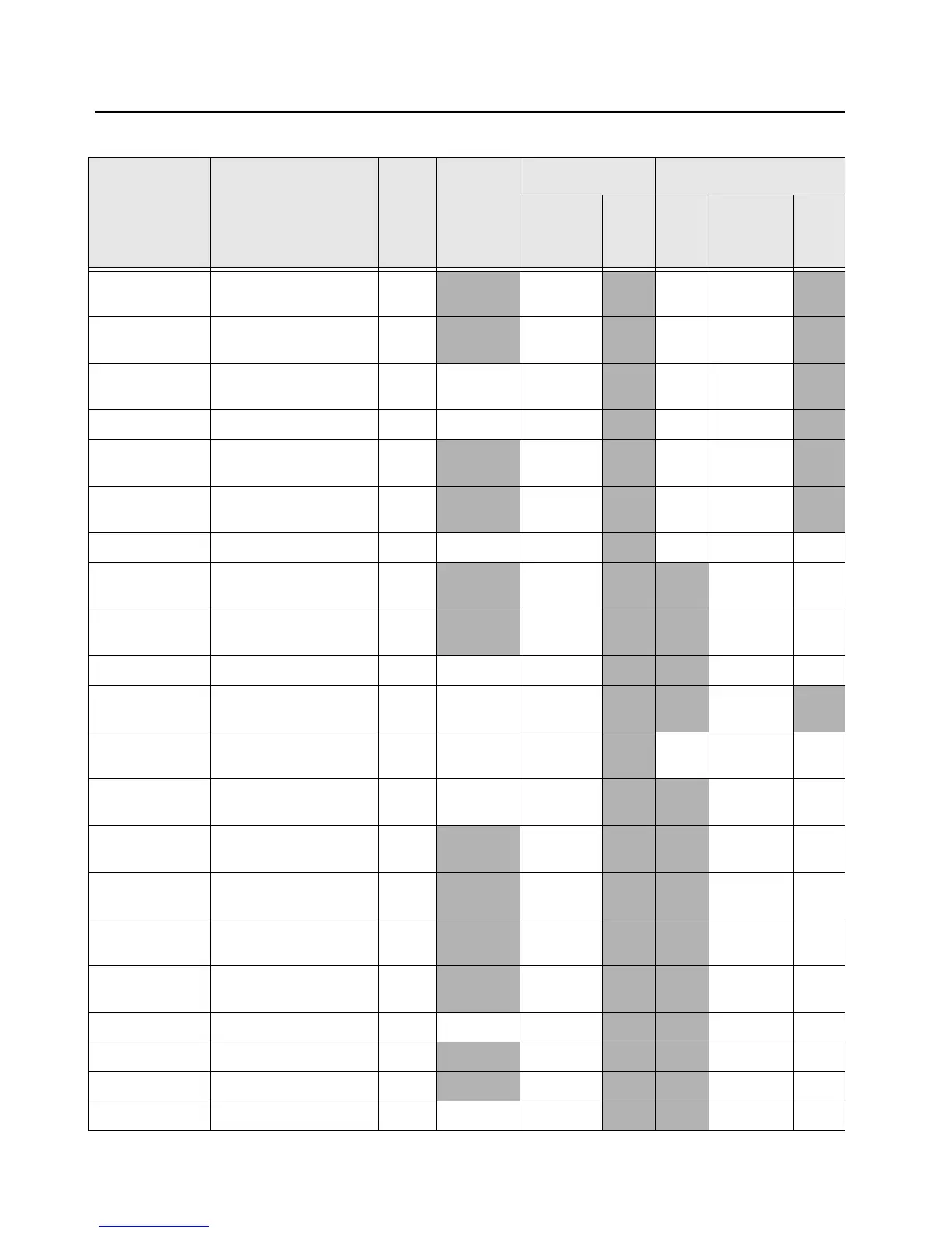
7-18 Troubleshooting Tables: List of Board and IC Signals
Unused and Unwired
OMAP Pin
M14 Output 0 Output
Unused and Unwired
OMAP Pin
N14 Output 0 Output
GPS_SHUTDO
WN
Shutdown to GPS D12 0 Output 0 Output
RF_RESET Reset to RF board A8 0 Output 0 Output
Unused and Unwired
OMAP Pin
B7 Output 0 Output
Unused and Unwired
OMAP Pin
B8 Output 1 Output
MMC_RESET MMC Card Reset C7 0 Output None 1 Output None
Unused and Unwired
OMAP Pin
J2
Input None Input None
Unused and Unwired
OMAP Pin
M8
Input None Input None
BT_USB_BOOT Bluetooth ‘boot’ signal P8 0 Output
None Input None
BT_AVR_RESE
T
Bluetooth AVR32 Reset
signal
M13 0 Output
None Input
KEY_FAIL_SWI
TCH
Enables keyload path
for MACE secure.
A12 1 Output 0 Output
SECURE_CLEA
R
Secure/Clear switch M6 TBD Input
PU Input None
RTA3 Channel selector rotary
switch
N11
Input None Input 3
RTA2 Channel selector rotary
switch
K14
Input None Input None
RTA1 Channel selector rotary
switch
J13
Input None Input None
RTA0 Channel selector rotary
switch
K13
Input None Input None
EMERGENCY Emergency pushbutton N7 0=Pressed Input
PU Input PU
TG1 Toggle switch N6
Input PU Input PU
TG0 Toggle switch N8
Input PU Input PU
SB2 Side button #2 N5 0=Pressed Input
PU Input PU
Table 7-12. Overall GPIO pin functions across multiple boards (Continued)
Signal Name Description
Pin
or
Ball #
Active
State
SW Initialized HW Reset
Direction
*
PU State Direction
*
PU
or
PD

 Loading...


