October 27, 2004 9964416H03-O
3-6 Codeplug Configuration: Aux Button Configuration
3.6 Aux Button Configuration
The final configuration item for the dual-radio system is to program a button on the control head to
switch between the mobile radios. This button is known as the Auxiliary Radio Button. On the W3
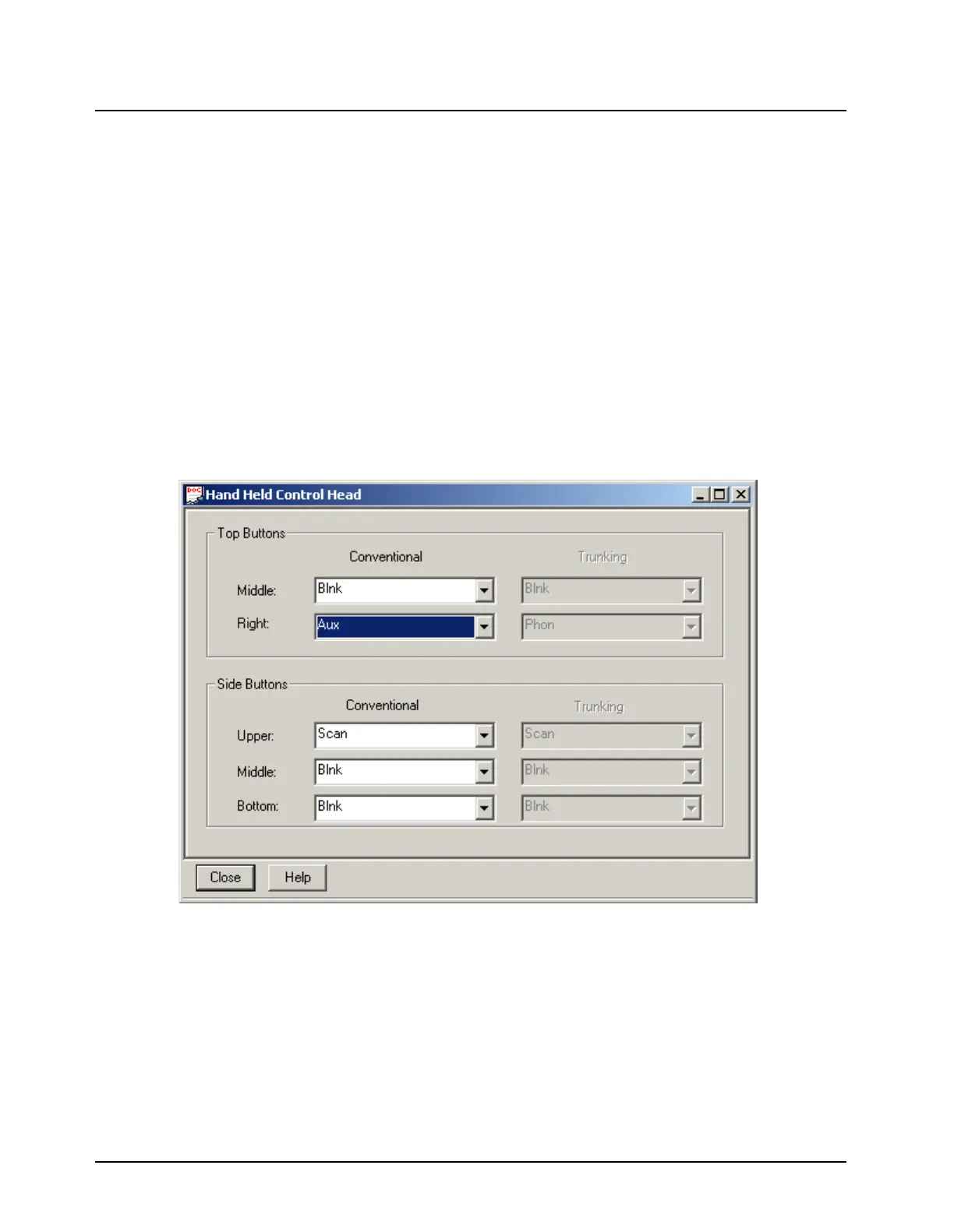
control head the Auxiliary Radio Button can be assigned to any of the programmable button
locations in the Radio Configuration->Controls->Control Head screen (Figure 3-6) in the ASTRO
25 Mobile CPS. In Figure 3-6, the Top-Right Button (T3) has been selected as the location of the
Auxiliary Radio Button.
Since there are no button indicators on the W3 control head, the only indication the user will have to
determine which radio is currently being selected is the “Radio Alias ID”. The “Radio Alias ID” is
momentarily displayed on the control head after a radio switch occurs. As a result, it is recommend
that Zone names be configured to display a unique value for each radio (ex: “R1” and “R2”). This will
allow the user to quickly determine which radio is selected by checking the Zone name displayed on
control head.
NOTE: Be sure to program the Auxiliary Radio Button to the same programmable button location for
both Conventional and Trunking in both the Primary and Auxiliary radios.
Figure 3-6. Aux Button Configuration Screen

 Loading...


