October 27, 2004 9964416H03-O
5-2 Dual-Radio Installation: Trunk Units
5.2.2 Cables
This section describes the installation of the dual-radio system cables.
5.2.2.1 Dual-Radio Cable
The 3064426H01 cable connects the Primary and Auxiliary radios to the W3-style HHCH (via the
quick-disconnect connector). Attach the yellow radio connector end of the 3064426H01 cable to the
front left of the Primary radio (female connector, labeled “Control Unit”). Securely tighten the two
screws. Attach the red radio connector end of the cable to the front left of the Auxiliary radio (female
connector, labeled ”Control Unit”). Securely tighten these two screws also. The quick-disconnect end
of the 3064426H01 cable will attach to the HHCH and is mounted in the operator’s compartment.
This end of the cable also contains the connections for the speakers, the emergency foot switch, and
the ignition sense.
5.2.2.2 Power and Ground Cables
Route the red radio power cables from both radios to the vehicle’s battery compartment, using
accepted industry methods and standards. It is important that both power leads are connected to the
battery, rather than using one power lead through the vehicle and splitting it to both radios. This is
because it is possible to have both mobile radios transmit at the same time (OTAR, data, etc.) and
the power cable for each radio is rated to handle the maximum transmit current of that radio only.
Be sure to grommet the firewall hole to protect the cable. Remove the 15-amp (P/N 6580283E06) or
20-amp (P/N 6580283E07) fuse from the fuseholder and connect the red lead of the radio power
cable to the positive battery terminal using the hardware provided as shown in Figure 5-2. Connect
the black lead to a convenient solid chassis ground point. DO NOT connect the black lead directly to
the battery’s negative terminal.
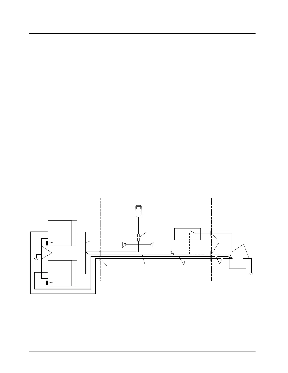
Figure 5-2. Cabling Interconnect Diagram for W3 Remote Mount
RADIO COMPARTMENT
OPERATOR COMPARTMENT VEHICLE BATTERY
COMPARTMENT
A good chassis connection via the black primary
power cable is essential for radio operation and
to prevent damage to the radio and cable kit.
Connection to the vehicle frame is desirable.
VEHICLE
BATTERY
15A OR 20A
FUSE
PART OF
VEHICLE
WIRING
GROMMET
GROMMET
RADIO POWER CABLE
(RED/HOT)
IGNITION LEAD
(ORANGE)
DUAL
RADIO
CABLE
SPEAKER 2
3A OR 4A
FUSE
RADIO
POWER CABLE
(BLK/GROUND)
AUXILIARY
RADIO
(-)
(+)
SPEAKER 1
CAUTION
MAEPF-27994-1-A
REAR
CONNECTOR
PRIMARY
RADIO
REAR
CONNECTOR
QUICK DISCONNECT
CONNECTOR
HAND HELD
CONTROL HEAD
VEHICLE
IGNITION SWITCH
ON/ACC

 Loading...


