9964416H03-O October 27, 2004
Chapter 5 Dual-Radio Installation
5.1 Installation Planning
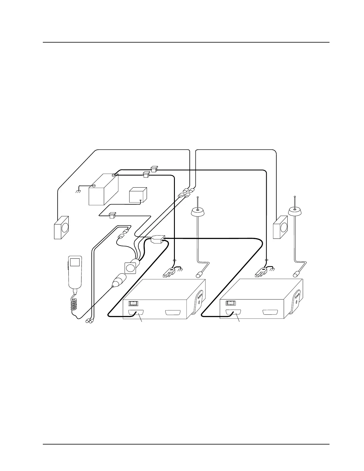
The ASTRO Digital XTL 5000 Dual Radio System consists of several different components (see
Figure 5-1) and some preliminary planning should be completed before beginning actual system
installation. The W3 Handheld Control Head (HHCH), emergency footswitch, and speakers mount in
the operator’s compartment. It is recommended that the radios be mounted in the vehicle’s trunk. Be
sure the chosen locations for all housings do not expose the units to dirt or moisture.
Figure 5-1. ASTRO Digital XTL 5000 Dual-Radio W3 Handheld Control Head System
5.2 Trunk Units
This section describes trunk unit installations.
5.2.1 Radio Mounting
Refer to Section 2.2, Radio Mounting, of the ASTRO XTL 5000 Digital Mobile Radio Installation
Manual (P/N 6881096C72).
BATTERY
IGNITION LEAD
SPEAKER
SPEAKER
EMERGENCY
FOOT SWITCH
FUSE
BLOCK
(+)
(-)
FIREWALL
HOLE
ANTENNA
CONNECTION
ANTENNA
CONNECTION
DC
POWER
CABLE
DUAL
RADIO
CABLE
FIREWALL
HOLE
DC
POWER
CABLE
PRIMARY
RADIO
HANDHELD
CONTROL
HEAD
FUSE
FUSE
FUSE
J5
P506
J6
AUXILIARY
RADIO
J5
YELLOW
RED
P506
J6
MAEPF-27995-1-A

 Loading...


