6815851H01-O June 3, 2005
Standard Configurations: Planning the Installation 2-3
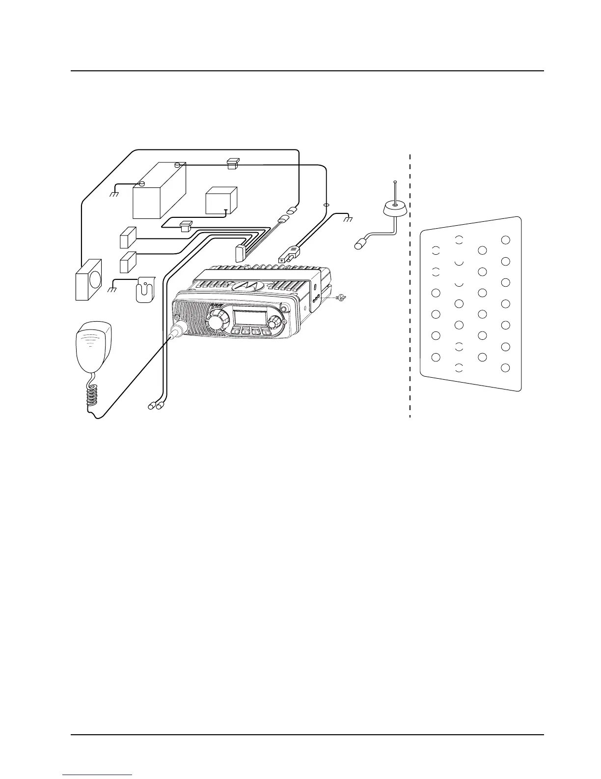
2.1.2 Wiring Diagrams
Figure 2-4 shows the wiring diagram the possible configurations. The title under the figure identifies
the control head configurations. Use the diagram when planning the installation.
Figure 2-4. Radio Installation with transceiver
(For complete pin configuration, see Figure 3-6.)
BATTERY
HORN
RELAY
LIGHT
RELAY
MIC
CLIP
SPEAKER
(Optional)
MIC
EMERGENCY
SWITCH
FUSE
FUSE
BLOCK
(+)
(-)
RED LEAD
FUSE
FIREWALL
HOLE
ANTENNA
CONNECTION
ANTENNA
IGNITION CABLE
P2
(SEE J2
PINOUT)
DC
POWER
CABLE
J2
REAR ACCESSORY CONNECTOR
MOUNTING
SCREW
TRUNNION
1
7
8
14
13
20
21
26
SPKR-
SPKR+
VIPOUT 2
12V
(RELAY)
VIPOUT 1
12V
(RELAY)
GROUND
EMERGENCY
IGNITION

 Loading...


