6815851H01-O June 3, 2005
Options and Accessories Installation: Accessory Connector Assembly Details (P2) 3-9
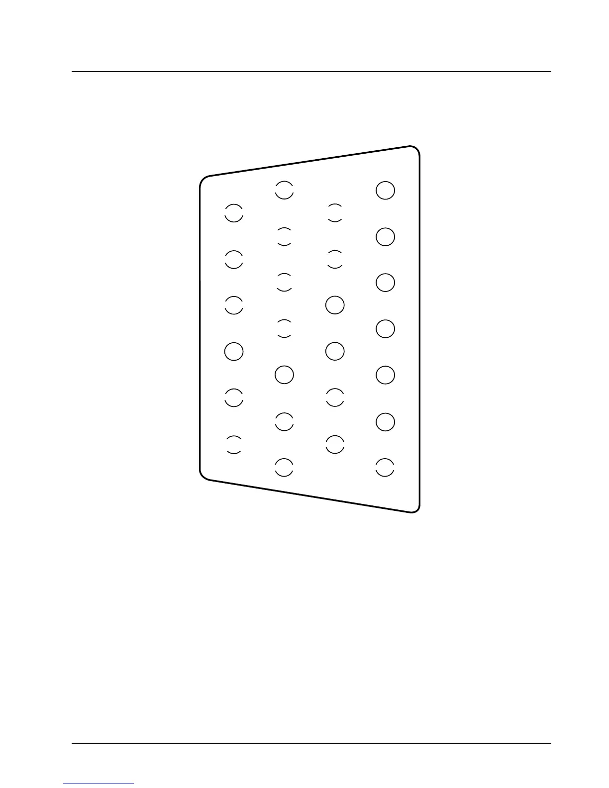
3.3.4 Transceiver Rear Accessory Jack Connection
Figure 3-6 shows the complete pin configuration for the J2 rear accessory jack and Table 3-2
explains the functions of each of the pins.
Figure 3-6. Rear Accessory Jack Pin Configuration (J2) (Radio Side)
AUX
MIC
PTT
USB+
CTS
RTS
USB-
TXD
BUS-
BUS+
RXD
MAEPF-27619-O
1
7
8
14
13
20
21
26
EMERGENCY
GROUND
GROUND
RX FILT
AUDIO
MONITOR
RESET
SPKR-
SWB+
SPKR+
VIP
OUT 1
VIP
OUT 2
ONE
WIRE
IGNITION
BUSY
USB
PWR
CHAN
ACT

 Loading...


