June 3, 2005 6815851H01-O
2-6 Standard Configurations: Power Cable and Ignition
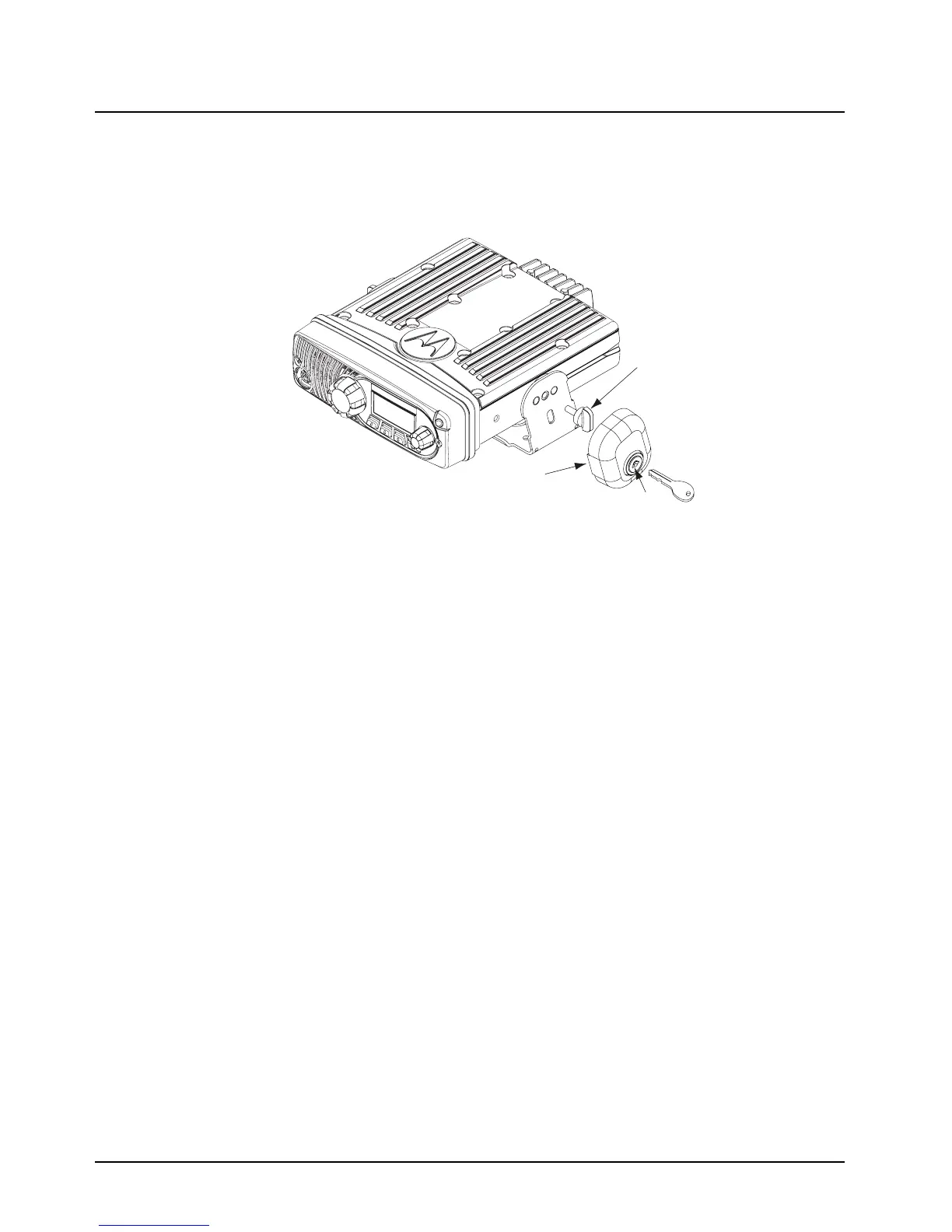
2.2.2 Locking Kit (Optional)
If an optional locking kit is used (shown in Figure 2-8), position the lock bottom housing on the
trunnion before installing the radio mounting screws. Then slip the top lock housing on and remove
the key. You can install the lock on either side of the radio, and by rotating it 180°, you can also install
it on dash installations.
Figure 2-8. Locking Kit (Optional)
2.3 Power Cable and Ignition
Route the red radio power cable from the radio to the vehicle’s battery compartment, using accepted
industry methods and standards. Be sure to grommet the firewall hole to protect the cable. Remove
the 15-amp (part number 6580283E06) or 20-amp (part number 6580283E07) fuse from the
fuseholder and connect the red lead of the radio power cable to the positive battery terminal using
the hardware provided as shown in Figure 2-9. Connect the black lead to a convenient solid chassis
ground point. DO NOT connect the black lead directly to the battery’s negative terminal.
Always connect the IGNITION LINE (thin red wire) located at the rear of the radio to the vehicle's
ignition switch (see Figure 2-9). The radio is programmable through CPS to allow ignition to disallow
the radio from powering up without ignition or to power up with ignition.
Existing
Mounting
Screw
Lock
Lock
Housing

 Loading...


