June 3, 2005 6815851H01-O
3-2 Options and Accessories Installation: VIP Overview
3.1.2 Emergency Pushbutton, Footswitch, Horn Relay, and Light Relay Installation
Perform the following installation procedure:
1. Select an appropriate place to mount the option or accessory hardware.
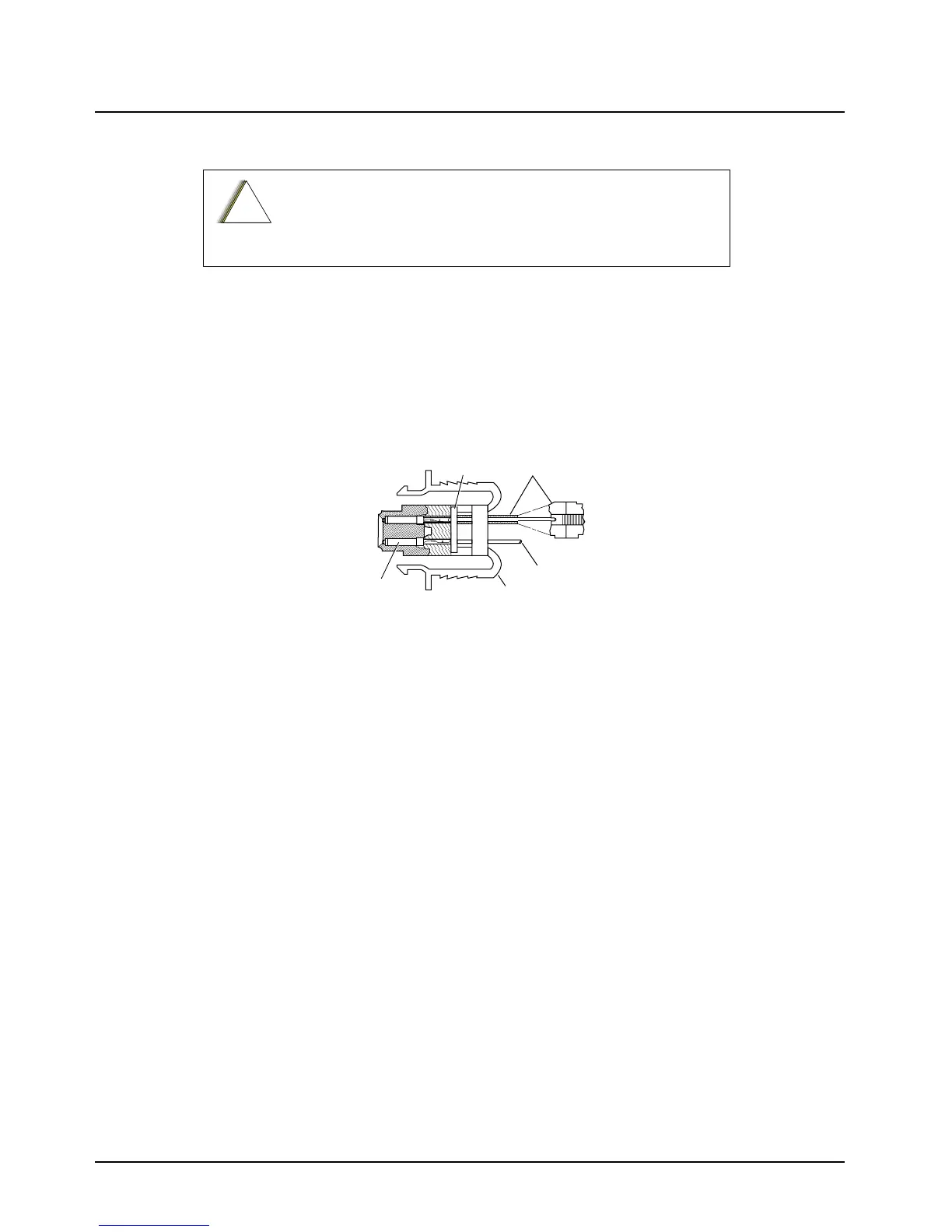
2. Connect the male-pin control leads (wires) to the VIP connector in the appropriate location
(see Table 3-1). Figure 3-1 shows how wires are plugged into the connector and how to use
an extraction tool to remove wires.
3. Route the accessory-to-control head cables under floor coverings or behind panels so that
the vehicle occupants do not snag or break the wires.
Figure 3-1. VIP Connector Detail
3.1.2.1 Emergency Pushbutton or Footswitch Installation
Mount the switch using the hardware that comes with the kit. Connect the emergency switch wires to
a ground pin and a VIP IN pin on the VIP connector.
1. Remove JU1008 (emergency to ground) from the control head remote back housing
(HLN6432_).
2. Place JU1007 (emergency to VIP IN 2) on the control head remote back housing
(HLN6432_).
3. Remove R84 (if installed) from the control head.
4. Install the emergency switch between pins 3 (VIP IN 2) and 20 (ground) of the control head
back connector.
3.1.2.2 Horn (External Alarm) Relay Installation
Mount the horn relay in a suitable location (normally under the dash). Connect the relay contacts
across the horn ring switch, typically found in the steering column. Connect the two control wires to a
SW B+ pin and a VIP OUT pin on the VIP connector.
3.1.2.3 Lights (External Alarm) Relay Installation
Mount the light relay in a suitable location (normally under the dash). Connect the relay contacts
across the headlamp ON/OFF switch. Connect the two control wires to a SW B+ pin and a VIP OUT
pin on the VIP connector.
CAUTION: When connecting the various microphones available,
make sure to attach the S-hook provided on the microphone cable
(see Figure 2-7 in Chapter 2) to the dash or remote mount trunnion
to avoid damage to the microphone control head interconnect.
!
C a u t i o n
VIP
GASKET
EXTRACTION
TOOL
WIRE
VIP
CONNECTOR
CRIMPED
RECEPTACLE
MAEPF-21424-O

 Loading...


