June 3, 2005 6815851H01-O
3-4 Options and Accessories Installation: Dash-Mount Accessory Installation
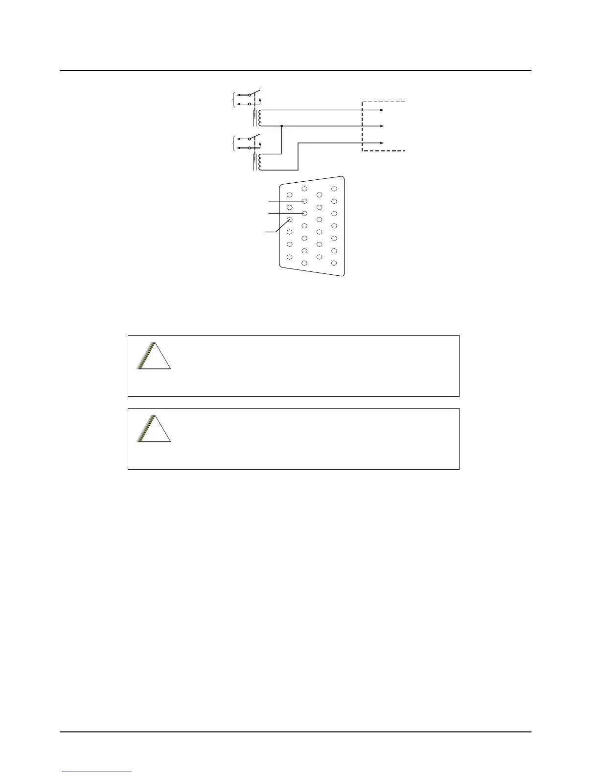
Figure 3-3. Horn/Light Wiring Diagram
3.2.3 External Speaker (HSN4031_)
The speaker kit includes a trunnion bracket that allows the speaker to be mounted in a variety of
ways. With the trunnion bracket, the speaker can mount permanently on the dashboard or in
accessible firewall areas. The trunnion allows the speaker to tilt for best operation. Mount the
speaker out of the way so that it will not be kicked or knocked around by the vehicle occupants.
Mount the speaker as follows:
1. Use the speaker mounting bracket as a template to mark the mounting hole locations.
2. Use the self-drilling screws provided to fasten the trunnion.
3. Attach the speaker and fasten to the trunnion with two wing screws.
4. Route the speaker wires under the carpet or floor covering, or behind the kick panels. Be sure
the wires are out of the way and will not be snagged and broken by the occupants of the
vehicle.
CAUTION: DO NOT use an external speaker which exceeds 7.5W
or is below 8 Ohm. Use ONLY HSN4031_ speaker kit
CAUTION: DO NOT ground the radio's speaker leads. This system
has a floating speaker output (dc voltage on both leads); damage
to the audio circuit will result if either lead is grounded or if they are
shorted together.
CONNECT
ACROSS HORN
RING SWITCH
CONNECT
ACROSS HEAD
LAMP SWITCH
SPST
N.O.
RELAY
12V COIL
12V COIL
VIP OUT 1
SWB+
VIP OUT 2
SPST
N.O.
RELAY
ACCESSORIES
CONNECTOR
PIN 1
PIN 24
PIN 19
MAEPF-27618-O
SWB+
VIP OUT 2
(LIGHTS)
VIP OUT 1
(HORN)
1
7
8
14
13
20
21
26
!
C a u t i o n
!
C a u t i o n

 Loading...


