June 3, 2005 6815851H01-O
3-10 Options and Accessories Installation: Accessory Connector Assembly Details (P2)
1
This pin must be connected to ground by jumper on accessory cable if emergency is disabled, even if disabled by
CPS. If enabled, this line must be grounded via a switch, which is normally closed. The emergency debounce time
is programmable via CPS.
2
Pulling this line to ground will activate PTT function, activating the AUX_MIC input.
3
Fixed level (independent of volume level) received audio signal, including alert tones. Flat or de-emphasis are pro-
grammed by CPS. Output voltage is approximately 100 mVrms per 1kHz of deviation. The DC offset is 1.4V.
4
This output is used to detect when a rear microphone accessory is taken off-hook, to override PL to alert the user
to busy traffic prior to transmitting.
5
This microphone signal is independent of the microphone signal on the front accessory connector. The nominal
input level is 80mVrms for 60% deviation but can also support 300 mVrms for future APCO accessories. The DC
impedance is 660 ohms and the AC impedance is 560 ohms.
Note: Please see the XTL 1500 Basic Service manual (Motorola publication part number 6815853H01) for more
detailed descriptions of these pins.
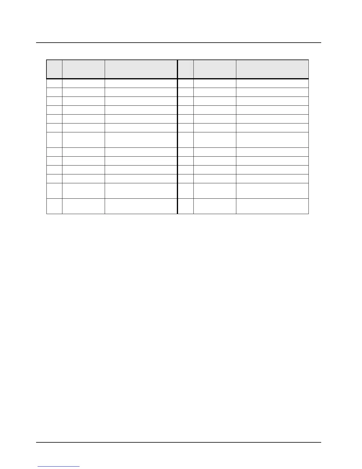
Table 3-2. Rear Accessory Jack Pin Functions
Pin
No.
Pin Name Pin Function
Pin
No.
Pin Name Pin Function
1 GND Ground 14 GND Ground
2 BUS+ SB9600 BUS+ Data 15 EMERGENCY Emergency
1
3 BUS- SB9600 BUS- Data 16 PTT* Pus h To Tal k
2
4 TXD RS232 Transmit Data 17 ONE WIRE One-Wire Data
5 RXD RS232 Receive Data 18 VIP OUT 1 Vehicular Interface Output
6 USB- USB - (Data) 19 VIP OUT 2 Vehicular Interface Output
7 USB+ USB + (Data) 20 SPKR+ Speaker + (3.2 ohm
minimum impedance)
8 RESET SB9600 RESET 21 RX FILT AUDIO Receive Filtered Audio Out
3
9 BUSY SB9600 BUSY 22 MONITOR Monitor Overrides PL
4
10 CTS RS232 Clear-To-Send 23 AUX MIC Rear Microphone Input
5
11 RTS RS232 Request-To-Send 24 SW B+ Switched Battery Voltage
12 USB PWR USB Power (5V from USB
accessory/cable)
25 Ignition Ignition Sense
13 CHAN ACT Channel Activity (qualified
received signal)
26 SPKR- Speaker - (8 ohm minimum
impedance)

 Loading...


