6815851H01-O June 3, 2005
Options and Accessories Installation: Accessory Connector Assembly Details (P2) 3-11
1
As indicated for front and rear connectors
2
Pin function as a true “DCE” device according to EIA standard
1
EIA standard
2
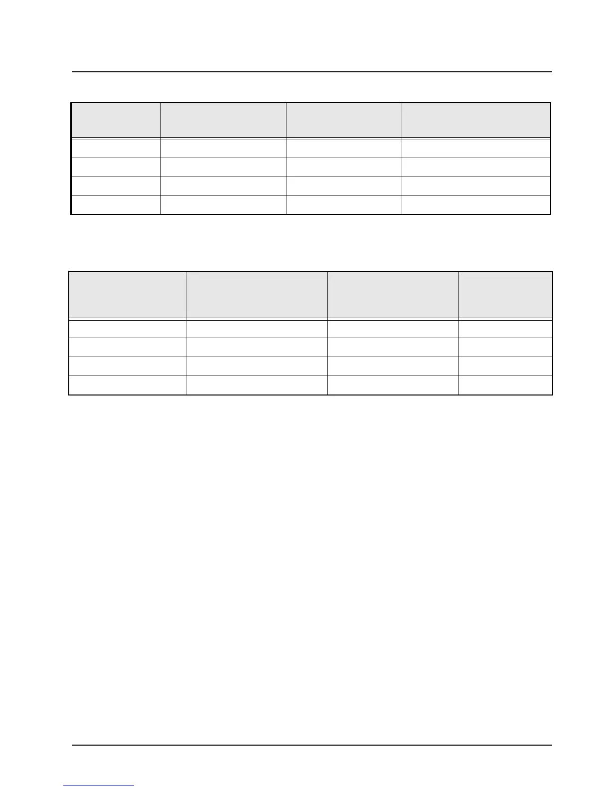
The DB9 (female) serial port cable can be added to the P2 rear accessory cable (Figure 3-5).
Note: TX to RX and RTS to CTS, not “same to same” (e.g., not TX to TX).
Table 3-3. Rear Connector and Front Connector Naming Schemes
J2 Pin Number J2 Pin Name
1
Pin Alternate Name
EIA Compatible Name at
Rear Connector J2
2
J2-4 UARTA_TX No change TX_DCE
J2-5 UARTA_RX No change RX_DCE
J2-10 UARTA_CTS Becomes RTS RTS_DCE
J2-11 UARTA_RTS Becomes CTS CTS_DCE
Table 3-4. How to Connect to a Computer
1
(DTE Device)
Radio Pin Direction
DB9 (Female) Serial Port
Connector
2
= DCE
Interface
DB9 (Male) Serial Port
Connector = DTE
Interface
Data Device Pin
Direction
Output TX_DCE = pin 2 pin 2 = RX_DTE Input
Input RX_DCE = pin 3 pin 3 = TX_DTE Output
Output RTS_DCE = pin 8 pin 8 = CTS_DTE Input
Input CTS_DCE = pin 7 pin 7 = RTS_DTE Output

 Loading...


