6815851H01-O June 3, 2005
Standard Configurations: Power Cable and Ignition 2-7
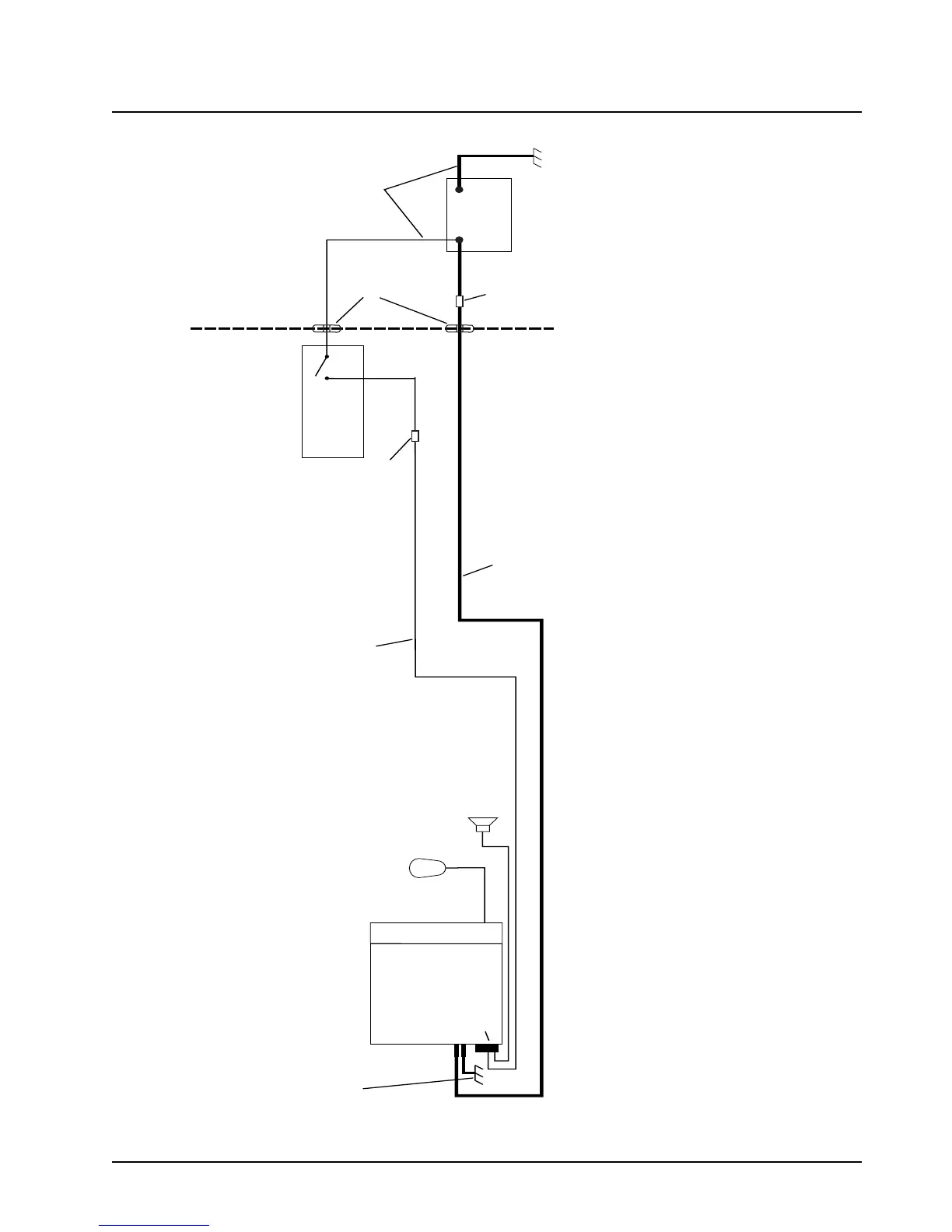
RADIO COMPARTMENT = OPERATOR COMPARTMENT
VEHICLE BATTERY
COMPARTMENT
A good chassis connection via the black primary
power cable is essential for radio operation and
to prevent damage to the radio and cable kit.
Connection to the vehicle frame is desirable.
VEHICLE
BATTERY
15A OR 20A
FUSE
PART OF
VEHICLE
WIRING
VEHICLE
IGNITION SWITCH
ON/ACC
GROMMET
RADIO POWER CABLE
(RED/BATTERY HOT)
RADIO IGNITION
CABLE (thin RED)
SPEAKER
(Optional)
3A OR 4A FUSE
MICROPHONE
RADIO POWER CABLE (BLK/GROUND)
RADIO
(-)
(+)
CAUTION
MAEPF-27646-B
Rear connector
CH
SEE NOTE
Caution: Always wire the radio’s IGNITION line to the car’s ignition switch.
Figure 2-9. Cabling Interconnect Diagram for Dash Mount

 Loading...


