Section 3: 1-2 Controller Circuits
Section : 6881091C63-F
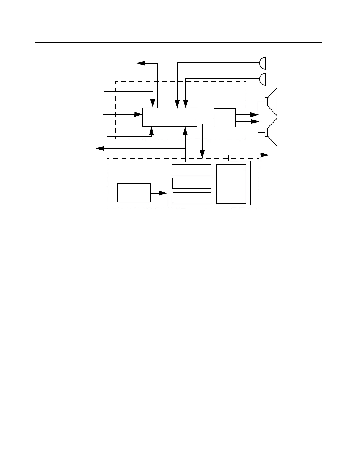
Figure 3-1 Controller Block Diagram
1.3 Radio Power Distribution
The DC power distribution throughout the radio board is shown in Figure 3-2. Voltage regulation for
the controller is provided by 4 separate devices; U0651 (MC78M05) 5V, U0641 (LM2941) 9.3V,
U0611 (LM2941) SWB+ limited to 16.5V and VSTBY 5V (a combination of R0621 and VR0621). An
additional 5V regulator is located on the RF section.
The DC voltage applied to connector J0601 supplies power directly to the electronic on/off control,
RF power amplifier, 16.5V limiter, 9.3V regulator, Audio PA and 5.6V stabilization circuit. The 9.3V
regulator (U0641) supplies power to the 5V regulator (U0651) and the 6V voltage divider Q0681.
Regulator U0641 is used to generate the 9.3 volts required by some audio circuits, the RF circuitry
and power control circuitry. Input and output capacitors (C0641 and C0644 / C0645) are used to
reduce high frequency noise. R0642 / R0643 set the output voltage of the regulator. If the voltage at
pin 1 is greater than 1.3 volts the regulator output decreases and if the voltage is less than 1.3 volts
the regulator output increases. This regulator output is electronically enabled by a 0 volt signal on
pin 2. Q0661, Q0641 and R0641 are used to disable the regulator when the radio is turned off.
Voltage regulation providing 5V for the digital circuitry is done by U0651. Operating voltage is from
the regulated 9.3V supply. Input and output capacitors (C0651 / C0652 and C0654 / C0655) are
used to reduce high frequency noise and provide proper operation during battery transients. Voltage
sense device U0652 or alternatively U0653 provides a reset output that goes to 0 volts if the
regulator output goes below 4.5 volts. This is used to reset the controller to prevent improper
operation. Diode D0651 prevents discharge of C0652 by negative spikes on the 9.3V voltage.
External
Microphone
Internal
Microphone
External
Speaker
Internal
Speaker
SCI to
Control Head
Audio
PA
Audio/Signaling
Architecture
To Synthesizer
Mod
Out
16.8 MHz
Reference Clock
from Synthesizer
Recovered Audio
To RF Section
SPI
Digital
Architecture
µP Clock
5V
Regulator
(5VD)
RAM
EEPROM
FLASH
HC11FL0
ASFIC_CMP
Accessory &
5V
from Synthesizer
Section (5V_RF)
Connector
 Loading...