Controller Circuits Section 3: 1-3
Section : 6881091C63-F
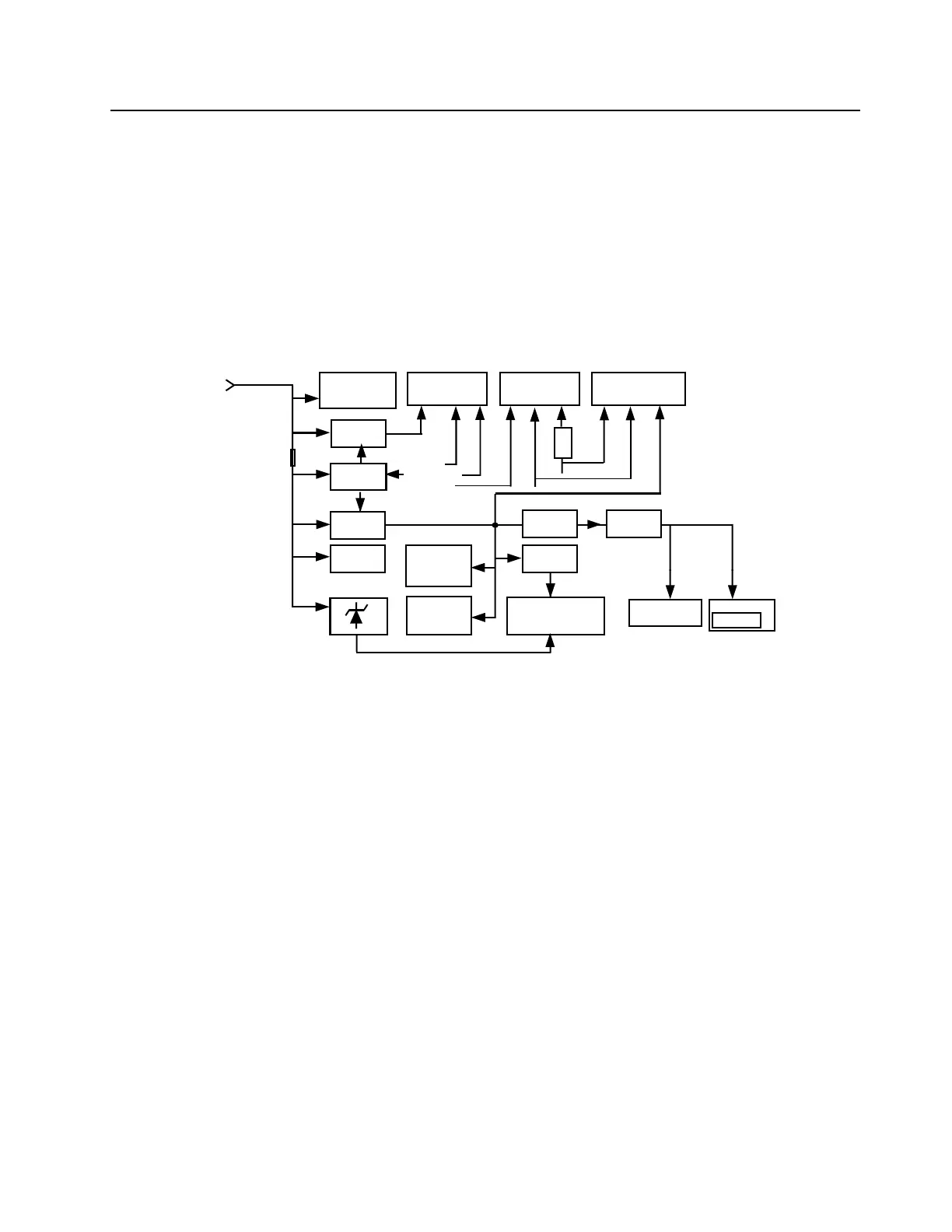
Transistor Q0681 and resistors R0681 / R0682 divide the regulated 9.3V down to about 6 volts. This
voltage supplies the 5V regulator, located on the RF section. By reducing the supply voltage of the
regulator, the power dissipation is divided between the RF section and the controller section.
The voltage VSTBY, which is derived directly from the supply voltage by components R0621 and
VR0621, is used to buffer the internal RAM. C0622 allows the battery voltage to be disconnected for
a couple of seconds without losing RAM parameters. Dual diode D0621 prevents radio circuitry from
discharging this capacitor. When the supply voltage is applied to the radio, C0622 is charged via
R0621 and D0621. To avoid the µP entering the wrong mode when the radio is switched on while
the voltage across C0622 is still too low, the regulated 5V supply charges C0622 via diode D0621.
Figure 3-2 DC Power Distribution Block Diagram
The voltage INT SW B+ from switching transistor Q0661 provides power to the circuit controlling the
audio PA output. The voltage INT SW B+ voltage is monitored by the µP through voltage divider
R0671 / R0672 and line BATTERY VOLTAGE. Diode VR0671 limits the divided voltage to 5.6V to
protect the µP.
Regulator U0611 is used to generate the voltage for the switched supply voltage output (SWB+) at
the accessory connector J0501 pin 13. U0611 is configured to operate as a switch with voltage and
current limit. R0611 / R0612 set the maximum output voltage to 16.5 volts. This limitation is only
active at high supply voltage levels. The regulator output is electronically enabled by a 0 volt signal
on pin 2. Q0661, Q0641 and R0641 are used to disable the regulator when the radio is turned off.
Input and output capacitors (C0603 and C0611 / C0612) are used to reduce high frequency noise.
Diode VR0601 acts as protection against transients and wrong polarity of the supply voltage.
Fuse F0401 prevents damage of the board in case the FLT A+ line is shorted at the control head
connector.
VCOBIC
FRACTN
VSTBY
5V_RF
9.3V
FLT_A+
5VD
SWB+
Option Board
40 Pin Connector
PA, Driver
Antenna Switch
Control Head
12 Pin Connector
Accessories
20 Pin Connector
J0601
13.2V
PASUPVLTG
FLT_A+
16.5V
Limiter
ON / OFF
Control
ASFIC_CMP
5.6V
Ignition
Emergency
ON/OFF
9.3V
Regulator
Audio PA
6V
Regulator
5V
Regulator
5VD
5V
Regulator
5V/
VDDA
MCU
µP, RAM,
FLASH & EEPROM
PCIC,
TX Amp
Temp Sense
RX RF Amp
IF Amp
F0401
 Loading...