Controller Board Audio and Signaling Circuits Section 3: 1-15
Section : 6881091C63-F
2.4 Receive Audio Circuits
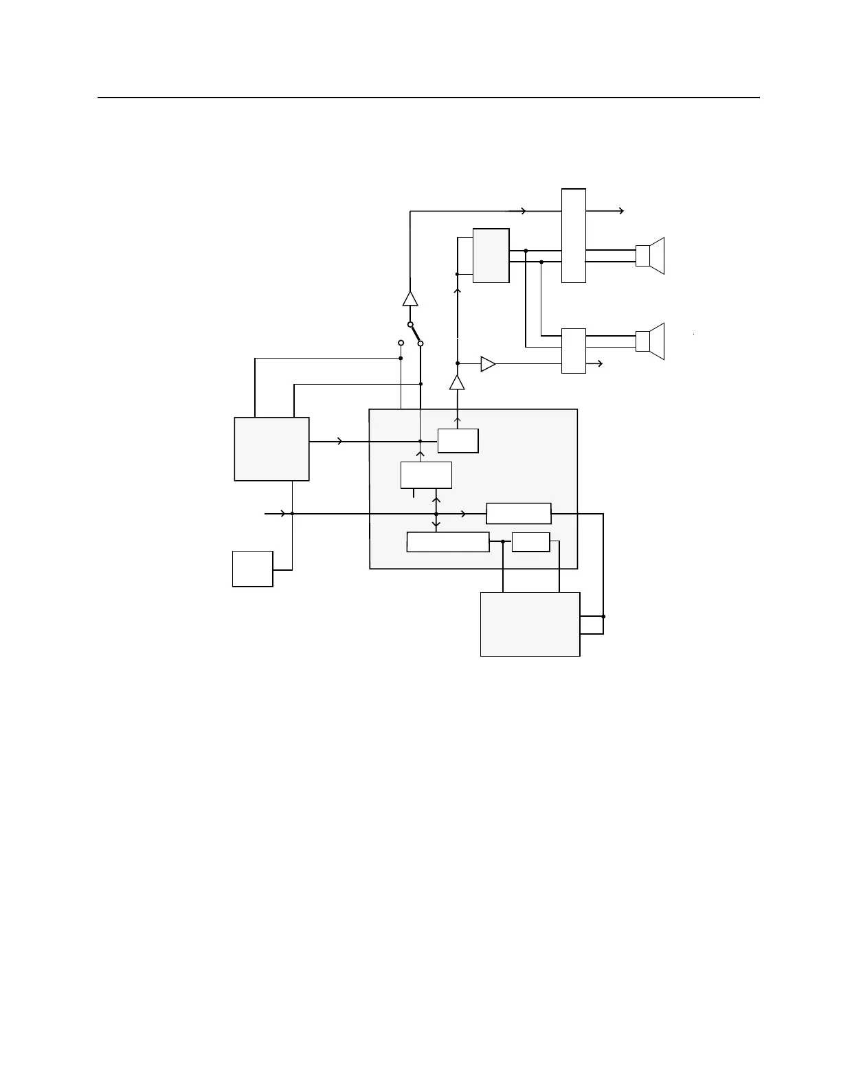
Refer to Figure 3-5 for reference for the following sections.
Figure 3-5 Receive Audio Paths
2.4.1 Squelch Detect
The radio’s RF circuits are constantly producing an output at the discriminator (IF IC). This signal
(DISC AUDIO) is routed to the ASFIC CMP’s squelch detect circuitry input DISC (U0221-2). All of
the squelch detect circuitry is contained within the ASFIC CMP. Therefore from a user’s point of
view, DISC AUDIO enters the ASFIC CMP, and the ASFIC CMP produces two CMOS logic outputs
based on the result. They are CH ACT (U0221-16) and SQ DET (U0221-17).
The squelch signal entering the ASFIC CMP is amplified, filtered, attenuated, and rectified. It is then
sent to a comparator to produce an active high signal on CH ACT. A squelch tail circuit is used to
produce SQ DET (U0221-17) from CH ACT. The state of CH ACT and SQ DET is high (logic “1”)
when carrier is detected, otherwise low (logic “0”).
CH ACT is routed to the µP pin 84 while SQ DET is routed to the µP pin 83.
FLT/FLAT RX AUDIO
J0501
11
16
1
EXTERNA
SPEAKER
INTERNA
SPEAKER
ACCESSORY
CONNECTOR
CONTROLHEAD
CONNECTOR
HANDSET
AUDIO
7
2
3
J0401
INT
SPKR-
SPKR +
SPKR -
1
9
2
J0551
4110
INT
SPKR+
4
6
DISC
ASFIC_CMP
U0221
AUDIO
PA
U0271
IN
OPTION
BOARD
IN
OUT
VOLUME
ATTEN.
FILTER AND
DEEMPHASIS
17
MICRO
CONTROLLER
U0101
80
FROM
RF
SECTION
(IF IC)
LIMITER, RECTIFIER
FILTER, COMPARATOR
SQ DET
SQUELCH
CIRCUIT
16
PL FILTER
LIMITER
CH ACT
AUX RX
43
18
LS IO
U IO
AUDIO
83
84
39
URX OUT
17
J0451
EXPANSION
BOARD
DISC
AUDIO
34
28
35
85
IN
7
 Loading...