20 March 01, 2007 6809509A89-O
Disassembly
6. To replace, carefully align the rear housing to the front & flip assembly.
7. Gently press the housings together until they fit snuggly.
8. Replace the 4 housing screws and tighten to a final torque setting of 1.4 +/- 0.1 lbs. Do not
over tighten.
9. Flip over the phone & replace the 2 front housing cap screws & tighten to a final torque
setting of 1.4 +/- 0.1 lbs. Do not over tighten.
10. Replace the SIM, memory card, battery, and battery cover as described in the procedures.
Removing and Replacing the Transceiver Board Assembly
1. Remove the battery cover, battery, SIM, and rear housing as described in the procedures.
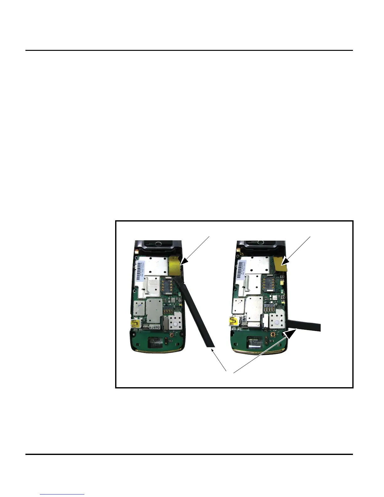
2. Use the plastic tweezers to pry loose the FLEX connector.
3. Lift the transceiver board assembly out of the front housing with the plastic tweezers. See
Figure 7.
4. To replace, insert the transceiver board assembly into the rear housing.
IMPORTANT During reassembly, make sure the PCB is not seated over the acoustic grommet.
5. Carefully and gently press the transceiver board into position and until it snaps into place.
6. Replace the rear housing, SIM, battery, and battery cover as described in the procedures.
G
This product contains static-sensitive devices. Use anti-static handling procedures
to prevent electrostatic discharge (ESD) and component damage.
061469o
Figure 7. Disconnecting the Flex from the Transceiver Board
Disassembly Tool
FLEX Connector
FLEX Connector
 Loading...