6809509A89-O March 01, 2007 27
Level 1 and 2 Service Manual Disassembly
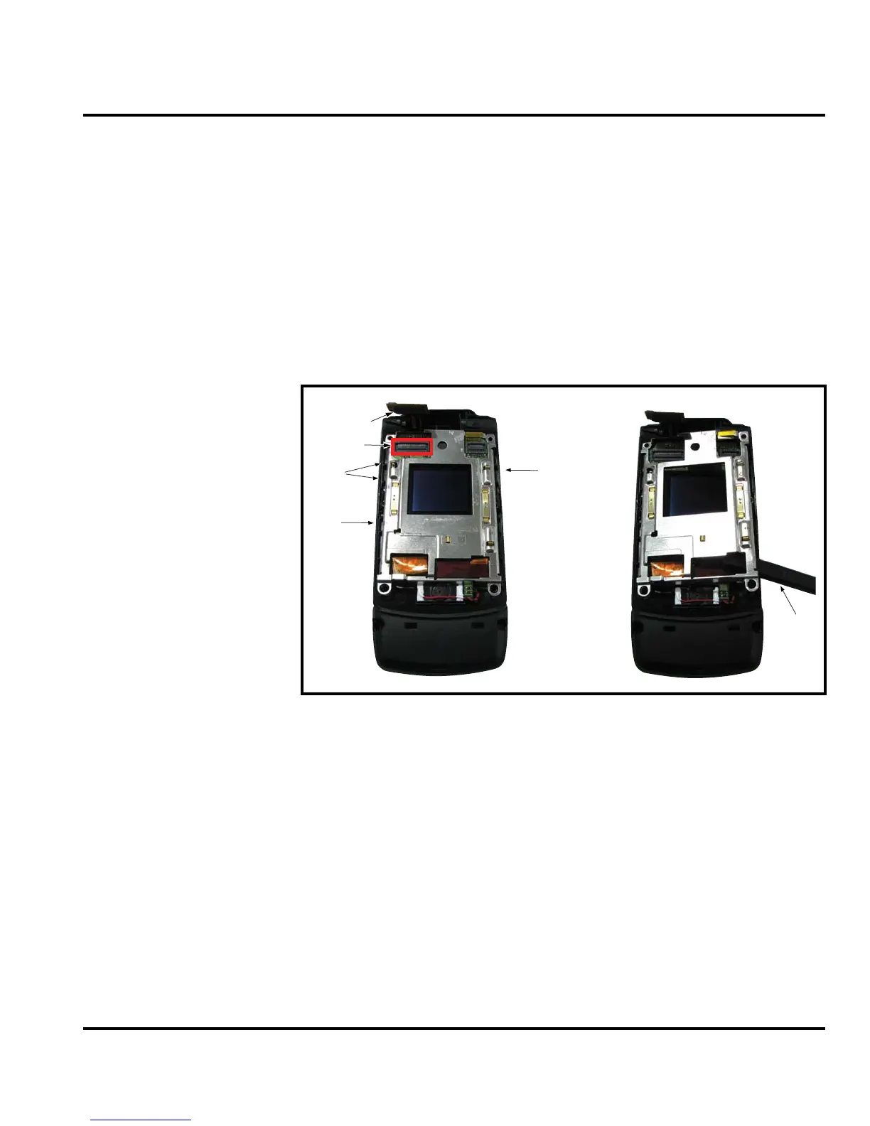
Removing and Replacing the Display Module Assembly
1. Remove the battery cover, battery, SIM, rear housing, transceiver board assembly, flip
assembly cover, CLI lens and camera assembly, as described in the procedures.
2. Use the disassembly tool to unseat the display module assembly flex connector from its
socket (see Figure 16)
3. Using the disassembly tool, carefully disengage the side hooks of the display bracket.
4. Lift the display bracket from the Flip pcb & housing.
5. Seperate the speaker from its adhesive by prying the speaker off using the disassemby tool.
6. Carefully and gently lift one corner of the display module assembly out of the flip assembly.
7. Avoid damage to the electrical components on the flex while carefully removing the
display module assembly from the flip assembly.
G
The flexible printed cable (FPC) (flex) is easily damaged. Exercise extreme care when
handling.
Figure 16. Display Module Assembly Flex Connector
Display Module Flex
Volume key
Camera key
Voice command key
ZIF connector
Disassembly tool
 Loading...