6 Installation and commissioning
455831400/02 EN
▪ If both low voltage and extra-low voltage are connected in the device, it
must be ensured that the circuits for extra-low voltage and for low voltage
in the connection area and in the cable are separated from each other
with double insulation.
▪ Devices with a plug connection may be connected via the device plug to
either only extra-low-voltage circuits or only low-voltage circuits.
Connection cable Terminals Permissible cross-section
Protective conductor ≥ all other conductors
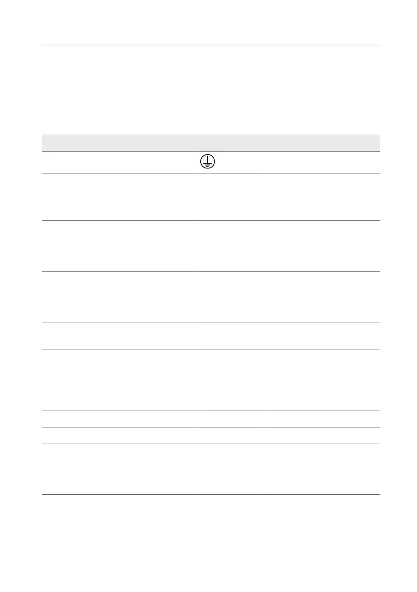
Micro-switch for oil temperature indi-
cator without interface
MT-ST160SK
12, 11, 14;
22, 21, 24;
32, 31, 34;
42, 41, 44
1.5...2.5mm²/16...12AWG
Micro-switch for oil temperature indi-
cator with interface
MT-ST160SK/TT
MT-ST160SK/TTM
12, 11, 14;
22, 21, 24;
32, 31, 34;
42, 41, 44
0.2...4mm²/24...12AWG
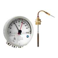
Micro-switch for all winding tempera-
ture indicators
MT-ST160W
MT-ST160WR
12, 11, 14;
22, 21, 24;
32, 31, 34;
42, 41, 44
0.2...4mm²/24...12AWG
2A current transformer for the wind-
ing temperature indicator
1)
3, 6 0.2...4mm²/24...12AWG
Measuring device for the winding
temperature indicator
1)
:
Gradient setting via
- voltmeter (MT-ST160W…)
- ohmmeter (MT-ST160WR…)
4, 5 0.14...1.5mm²/26...16AWG
Analog output
1)
(types TT, TTM) (+), (-) 0.2...1.5mm²/24...16AWG
Power supply
1)
(type TTM) 24V, 0V 0.2...1.5mm²/24...16AWG
Modbus RTU
1)
(type TTM)
A = "+" connection
B = "-" connection
COM = common ground
A, COM, B 0.2...1.5mm²/24...16AWG
Table6: Recommendation for connection cable (standard connections)
1)
Depending on the equipment version (optional)
It must be possible to apply a nominal voltage of at least 300V to all above-
listed connection cables. Rigid and flexible cables can be used.