6 Installation and commissioning
655831400/02 EN
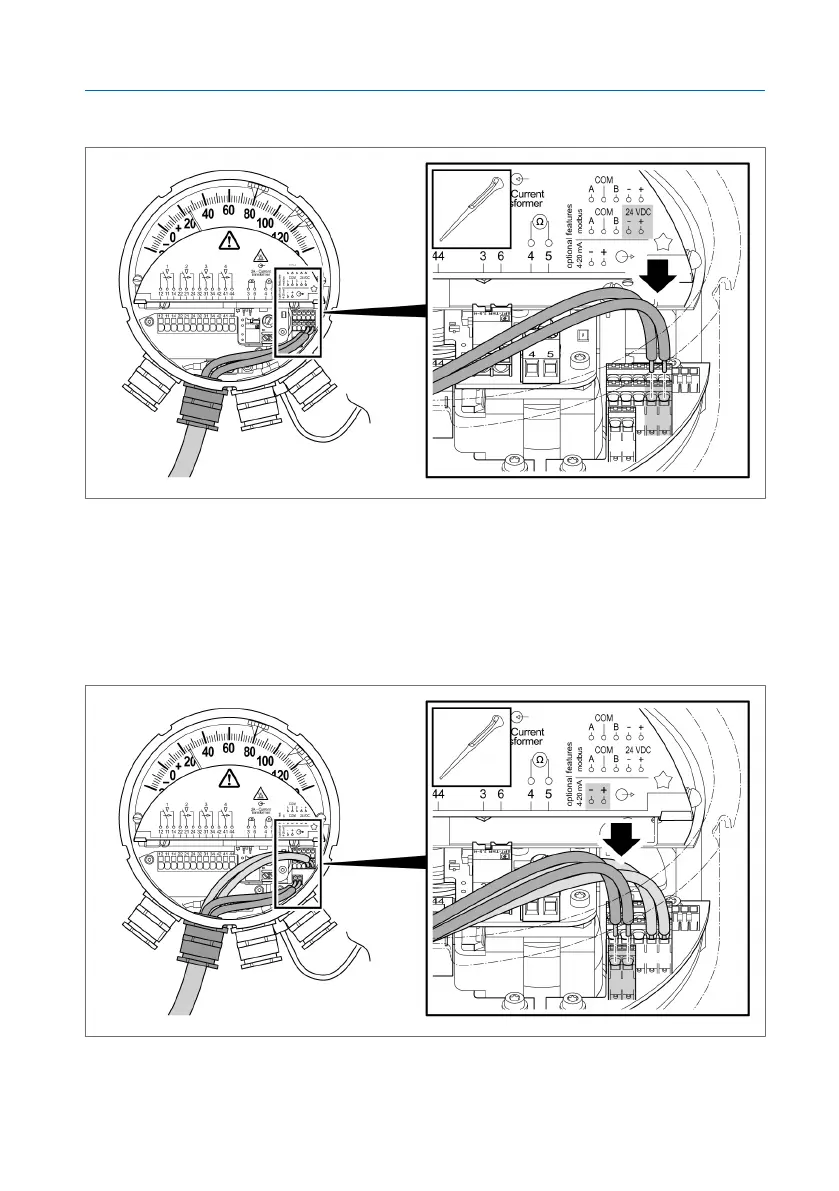
3. Release the actuator.
Figure47: Connecting the supply voltage
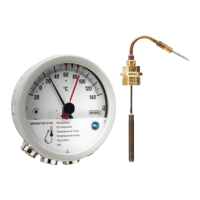
Connecting the 4...20mA analog output in accordance with the
connection diagram
1. Use the same method to attach the wires for the analog output to the ter-
minals "4…20mA(+/–)". Do so by pushing the wires through the opening
up to the stop.
Figure48: Connecting the analog output
2. Connect an evaluation unit without a driving input.