6
2.0 Installation
2.1 Location of the Controller
The Model 610A Controller should be installed in a weather-protected, non-hazardous
area. The f ollowing mounting hardware is available to facilitate installation:
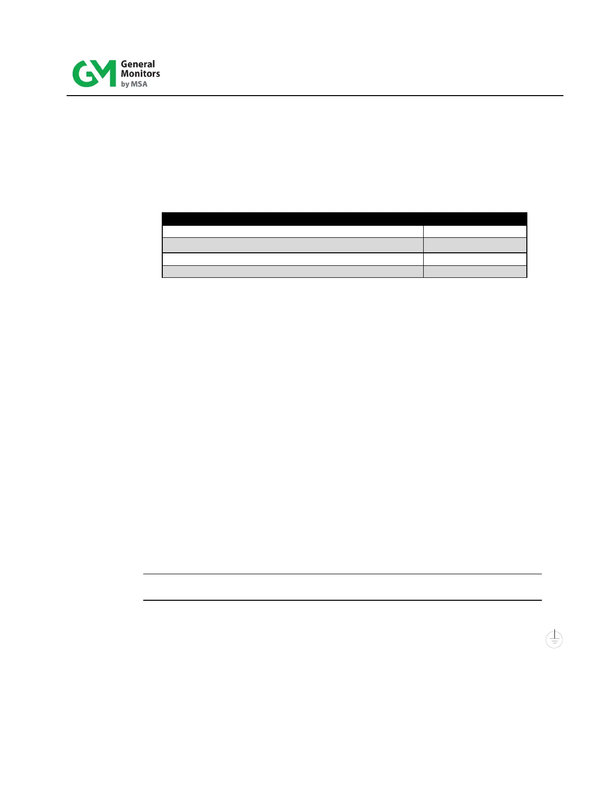
98mm (4”) panel mount frame
483 mm (19”) rack f rame (4 controllers)
Blank panel (one for each unused position in 19” f rame)
98mm (4”) wall mount bracket
Table 1: Model 610A Mounting Parts
The f ollowing are guidelines for mounting the controller:
• To minimize the possibility of electrical shock, mounting must be as free from
shock and vibration as possible, in a grounded enclosure that requires a tool f or
instrument removal.
• Even though the controller is RFI resistant, do not mount the controller i n c l ose
pro x imity to radio transmitters or similar equipment.
• It is recommended that a wiring service loop be used to facilitate gaining ac cess
to the alarm set points.
• Care should be taken to assure adequate ventilation.
• Do not mount the controller in a manner that restricts the natural convection
airflow.
• The controller operating temperature range is 0°C to 60°C (32°F to 140°F).
2.2 Power Connections
The system operates on nominal line power of 115 VAC, 50/60 Hz. Power mus t remain
disconnected until all other wiring connections are made.
NOTE: To eliminate accidental system shutdown, GMI does not provide a power on/of f
switch.
The f ollowing are wiring guidelines for the 610A Controller:
• If AC is to p ower the system, connect the line power supply to the terminals L, N,
located on the rear of the controller. Use accepted commercial wiring practices.
• Primary DC power may be used instead. Use any 24V no minal di rect current
supply with a minimum rating of 2 amperes.
• AWG 14 wire should be used to prevent excessive voltage drop.